
How to Use Heart Rate & Oximeter Sensor v2.0: Examples, Pinouts, and Specs
 Design with Heart Rate & Oximeter Sensor v2.0 in Cirkit Designer
Introduction
The Heart Rate & Oximeter Sensor v2.0 by DFROBOT is a compact and reliable module designed to measure heart rate and blood oxygen saturation (SpO2) levels. Utilizing photoplethysmography (PPG) technology, the sensor detects changes in blood volume by analyzing light absorption through the skin. This makes it ideal for real-time health monitoring in fitness, medical, and research applications.
Explore Projects Built with Heart Rate & Oximeter Sensor v2.0
 Open Project in Cirkit Designer
 Open Project in Cirkit Designer
 Open Project in Cirkit Designer
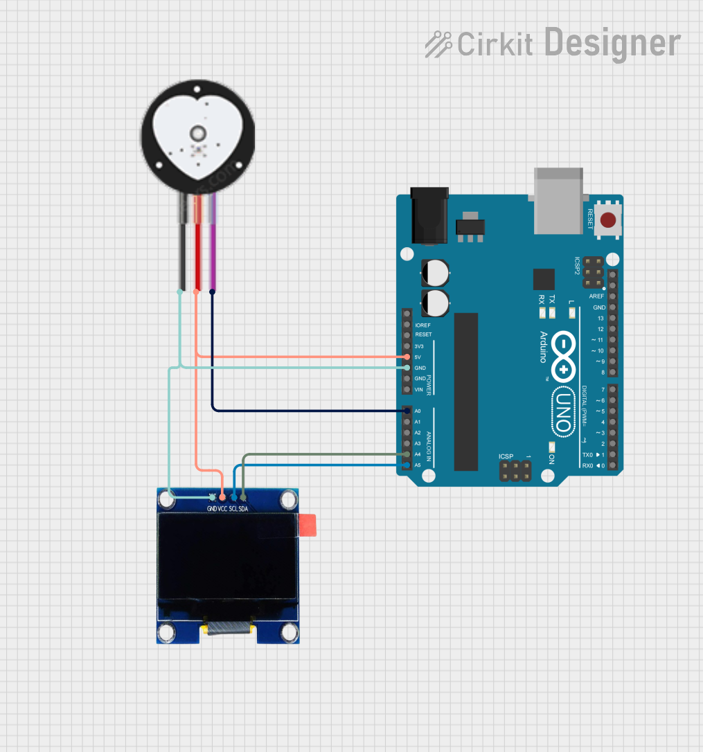 Open Project in Cirkit Designer
Explore Projects Built with Heart Rate & Oximeter Sensor v2.0
Open Project in Cirkit DesignerOpen Project in Cirkit DesignerOpen Project in Cirkit DesignerOpen Project in Cirkit DesignerCommon Applications
- Wearable health monitoring devices
- Fitness trackers
- Medical diagnostics and research
- IoT-based health monitoring systems
- Educational projects and prototyping
Technical Specifications
Below are the key technical details of the Heart Rate & Oximeter Sensor v2.0:
| Parameter | Specification |
|---|---|
| Operating Voltage | 3.3V - 5V |
| Operating Current | < 20mA |
| Communication Protocol | I2C |
| I2C Address | 0x57 (default) |
| Measurement Range | Heart Rate: 30-240 bpm |
| SpO2: 70%-100% | |
| Sensor Technology | Photoplethysmography (PPG) |
| Dimensions | 22mm x 20mm |
| Operating Temperature | -40°C to 85°C |
Pin Configuration
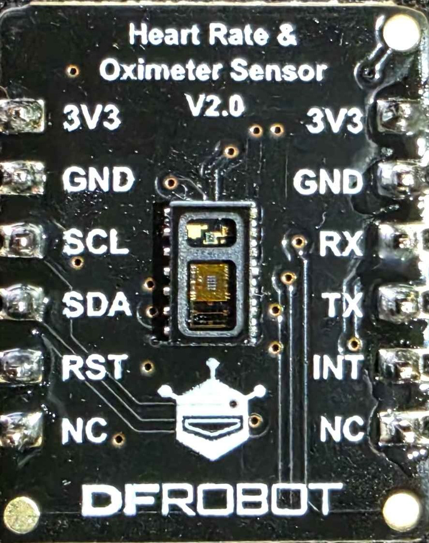
The sensor module has a 4-pin interface for easy integration into your circuit. Below is the pinout description:
| Pin | Name | Description |
|---|---|---|
| 1 | VIN | Power input (3.3V - 5V) |
| 2 | GND | Ground connection |
| 3 | SDA | I2C data line (connect to Arduino UNO SDA pin) |
| 4 | SCL | I2C clock line (connect to Arduino UNO SCL pin) |
Usage Instructions
How to Use the Sensor in a Circuit
- Power the Sensor: Connect the
VINpin to a 3.3V or 5V power source and theGNDpin to ground. - Connect I2C Lines:
- Connect the
SDApin to the SDA pin on your microcontroller (e.g., Arduino UNO A4 pin). - Connect the
SCLpin to the SCL pin on your microcontroller (e.g., Arduino UNO A5 pin).
- Connect the
- Install Required Libraries: Use the DFRobot-provided library or the MAX30102 library (if compatible) for Arduino to simplify communication with the sensor.
- Upload Code: Write or upload a program to read heart rate and SpO2 data from the sensor.
Sample Arduino Code
Below is an example Arduino sketch to read data from the Heart Rate & Oximeter Sensor v2.0:
#include <Wire.h>
#include "DFRobot_HeartrateOximeter.h" // Replace with the actual library name

DFRobot_HeartrateOximeter sensor;

void setup() {
  Serial.begin(9600); // Initialize serial communication
  Wire.begin();       // Initialize I2C communication

  // Initialize the sensor
  if (!sensor.begin()) {
    Serial.println("Failed to initialize Heart Rate & Oximeter Sensor!");
    while (1); // Halt execution if initialization fails
  }
  Serial.println("Sensor initialized successfully.");
}

void loop() {
  // Read heart rate and SpO2 data
  float heartRate = sensor.getHeartRate();
  float spO2 = sensor.getSpO2();

  // Check if valid data is available
  if (heartRate > 0 && spO2 > 0) {
    Serial.print("Heart Rate: ");
    Serial.print(heartRate);
    Serial.print(" bpm, SpO2: ");
    Serial.print(spO2);
    Serial.println(" %");
  } else {
    Serial.println("Waiting for valid data...");
  }

  delay(1000); // Wait 1 second before the next reading
}
Important Considerations and Best Practices
- Skin Contact: Ensure the sensor is in proper contact with the skin for accurate readings.
- Ambient Light: Avoid exposing the sensor to direct sunlight or strong ambient light, as it may interfere with measurements.
- Power Supply: Use a stable power source to prevent noise in the readings.
- I2C Address Conflicts: If using multiple I2C devices, ensure their addresses do not conflict. The default address for this sensor is
0x57.
Troubleshooting and FAQs
Common Issues and Solutions
No Data or Incorrect Readings:
- Ensure the sensor is properly connected to the microcontroller.
- Verify that the sensor is in contact with the skin.
- Check for ambient light interference and shield the sensor if necessary.
Sensor Initialization Fails:
- Confirm that the I2C connections (SDA and SCL) are correct.
- Ensure the correct library is installed and included in your code.
Inconsistent Readings:
- Verify that the power supply is stable and within the specified range.
- Avoid excessive movement during measurements, as it may affect accuracy.
FAQs
Q: Can this sensor be used with a Raspberry Pi?
A: Yes, the sensor supports I2C communication, which is compatible with Raspberry Pi. You will need to use appropriate libraries for Python.
Q: What is the maximum distance between the sensor and microcontroller?
A: For reliable I2C communication, the distance should typically not exceed 1 meter. Use proper pull-up resistors if longer distances are required.
Q: Can the sensor measure heart rate through clothing?
A: No, the sensor requires direct contact with the skin for accurate measurements.
Q: Is the sensor suitable for medical-grade applications?
A: While the sensor provides reliable data, it is not certified for medical-grade applications and should not be used for critical diagnostics.
By following this documentation, you can effectively integrate and utilize the Heart Rate & Oximeter Sensor v2.0 in your projects.