How to Use HC-05: Examples, Pinouts, and Specs
Introduction
The HC-05 is a Bluetooth module that allows for wireless communication between devices. It operates in the 2.4 GHz frequency range and is commonly used in embedded systems for connecting microcontrollers to smartphones or other Bluetooth-enabled devices. The module supports both master and slave modes, making it versatile for a wide range of applications.
Explore Projects Built with HC-05


Explore Projects Built with HC-05
Common Applications and Use Cases
- Wireless communication between microcontrollers and smartphones
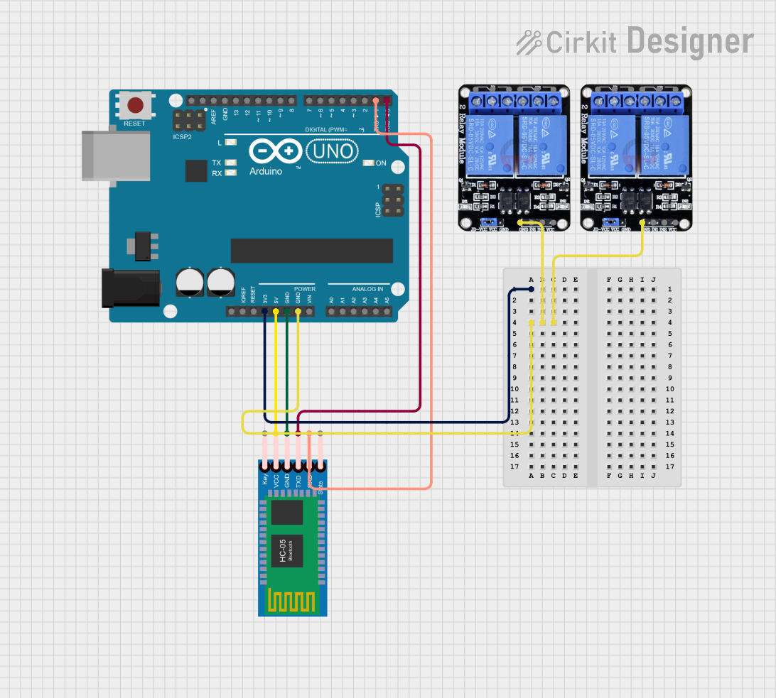
- Remote control of devices (e.g., home automation systems)
- Data logging and wireless data transfer
- Robotics and IoT (Internet of Things) projects
- Serial communication replacement for wired connections
Technical Specifications
The HC-05 module is designed for ease of use and reliable communication. Below are its key technical details:
Key Technical Details
- Bluetooth Version: 2.0 + EDR (Enhanced Data Rate)
- Frequency Range: 2.4 GHz ISM band
- Operating Voltage: 3.3V to 5V
- Current Consumption: ~30 mA (active mode), ~8 mA (idle mode)
- Communication Protocol: UART (Universal Asynchronous Receiver-Transmitter)
- Default Baud Rate: 9600 bps (configurable)
- Range: Up to 10 meters (line of sight)
- Modes: Master and Slave
- Dimensions: 37.5mm x 15.2mm x 3.5mm
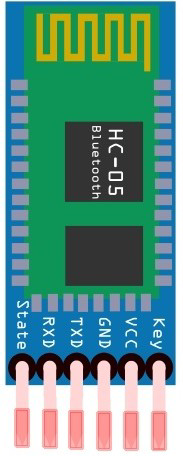
Pin Configuration and Descriptions
The HC-05 module typically has 6 pins. Below is the pinout and description:
| Pin | Name | Description |
|---|---|---|
| 1 | EN/KEY | Used to switch between command mode and data mode. Pull HIGH to enter command mode. |
| 2 | VCC | Power supply input (3.3V to 5V). |
| 3 | GND | Ground connection. |
| 4 | TXD | Transmit data pin. Sends serial data to the connected device. |
| 5 | RXD | Receive data pin. Receives serial data from the connected device. |
| 6 | STATE | Indicates the connection status (HIGH when connected, LOW when disconnected). |
Usage Instructions
The HC-05 module is straightforward to use in a circuit. Below are the steps and best practices for integrating it into your project.
How to Use the HC-05 in a Circuit
- Power the Module: Connect the VCC pin to a 3.3V or 5V power source and the GND pin to ground.
- Connect TXD and RXD:
- Connect the TXD pin of the HC-05 to the RX pin of your microcontroller.
- Connect the RXD pin of the HC-05 to the TX pin of your microcontroller. Use a voltage divider if your microcontroller operates at 5V logic levels to avoid damaging the HC-05.
- Set the Mode:
- For normal operation (data mode), leave the EN/KEY pin unconnected or LOW.
- To configure the module (command mode), pull the EN/KEY pin HIGH before powering the module.
- Pair the Module: Search for the HC-05 on your Bluetooth-enabled device. The default pairing code is usually
1234or0000. - Communicate: Use a serial communication protocol (e.g., UART) to send and receive data.
Important Considerations and Best Practices
- Voltage Levels: The RXD pin is not 5V tolerant. Use a voltage divider or level shifter if your microcontroller operates at 5V logic levels.
- Baud Rate: Ensure the baud rate of your microcontroller matches the HC-05's default baud rate (9600 bps) or configure it as needed in command mode.
- Antenna Placement: Avoid placing the module near metal objects or other RF sources to minimize interference.
- Command Mode: Use AT commands to configure the module (e.g., change the name, baud rate, or mode). Ensure the EN/KEY pin is HIGH before powering the module to enter command mode.
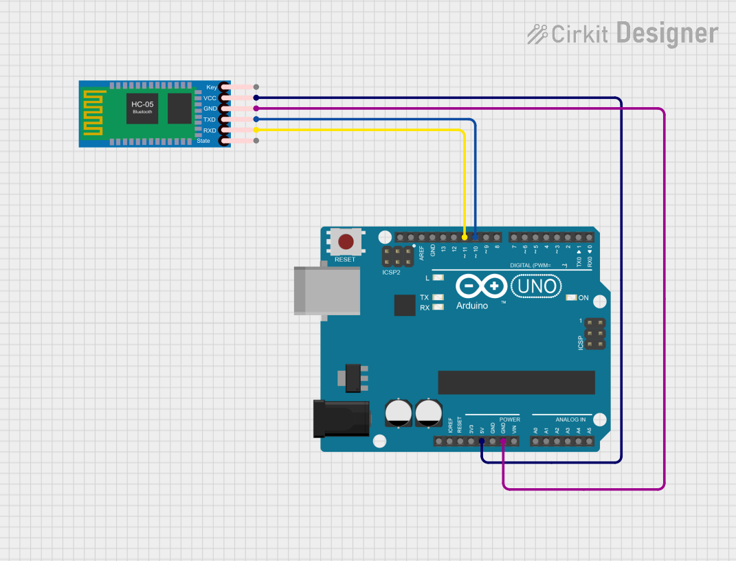
Example: Connecting HC-05 to Arduino UNO
Below is an example of how to use the HC-05 with an Arduino UNO to send and receive data.
Circuit Connections
- HC-05 VCC → Arduino 5V
- HC-05 GND → Arduino GND
- HC-05 TXD → Arduino RX (Pin 0)
- HC-05 RXD → Arduino TX (Pin 1) (use a voltage divider if needed)
Arduino Code
#include <SoftwareSerial.h>

// Define RX and TX pins for SoftwareSerial
SoftwareSerial BTSerial(10, 11); // RX = Pin 10, TX = Pin 11

void setup() {
  // Start the hardware serial communication
  Serial.begin(9600); // For communication with the PC
  // Start the Bluetooth serial communication
  BTSerial.begin(9600); // Default baud rate of HC-05

  Serial.println("HC-05 Bluetooth Module Test");
  Serial.println("Send data from the Serial Monitor to test.");
}

void loop() {
  // Check if data is available from the Bluetooth module
  if (BTSerial.available()) {
    char data = BTSerial.read(); // Read the data
    Serial.print("Received from Bluetooth: ");
    Serial.println(data); // Print the data to the Serial Monitor
  }

  // Check if data is available from the Serial Monitor
  if (Serial.available()) {
    char data = Serial.read(); // Read the data
    BTSerial.write(data); // Send the data to the Bluetooth module
    Serial.print("Sent to Bluetooth: ");
    Serial.println(data); // Print the data to the Serial Monitor
  }
}
Troubleshooting and FAQs
Common Issues and Solutions
Module Not Pairing:
- Ensure the HC-05 is powered and in range.
- Verify the pairing code (default is
1234or0000). - Check if the module is in data mode (EN/KEY pin LOW or unconnected).
No Data Transmission:
- Verify the TXD and RXD connections.
- Ensure the baud rate matches between the HC-05 and the microcontroller.
- Check for proper voltage levels on the RXD pin.
Unstable Connection:
- Avoid interference from other RF devices.
- Ensure a clear line of sight between the HC-05 and the paired device.
Cannot Enter Command Mode:
- Ensure the EN/KEY pin is HIGH before powering the module.
- Use a serial terminal to send AT commands and verify the response.
FAQs
Q: Can the HC-05 connect to multiple devices simultaneously?
A: No, the HC-05 supports only one-to-one communication.Q: How do I reset the HC-05 to factory settings?
A: Enter command mode and send theAT+ORGLcommand.Q: Can I use the HC-05 with a 5V microcontroller?
A: Yes, but use a voltage divider or level shifter for the RXD pin to avoid damage.Q: What is the difference between HC-05 and HC-06?
A: The HC-05 supports both master and slave modes, while the HC-06 operates only in slave mode.