Cirkit Designer Logo
Cirkit Designer
Your all-in-one circuit design IDE
Home / 
Component Documentation

How to Use GH1248 Hall Sensor: Examples, Pinouts, and Specs

Image of GH1248 Hall Sensor
Cirkit Designer LogoDesign with GH1248 Hall Sensor in Cirkit Designer

Introduction

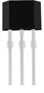
The GH1248 Hall Sensor, manufactured by GoChip Elec Tech, is a versatile electronic component designed to detect magnetic fields and convert them into electrical signals. This sensor is widely used in various applications, including proximity sensing, positioning, speed detection, and current sensing. Its ability to provide accurate and reliable measurements makes it an essential component in many electronic systems.

Explore Projects Built with GH1248 Hall Sensor

Use Cirkit Designer to design, explore, and prototype these projects online. Some projects support real-time simulation. Click "Open Project" to start designing instantly!
Arduino Nano ESP32 Hall Sensor Interface with LCD Display
Image of hall effect + speedometer: A project utilizing GH1248 Hall Sensor in a practical application
This circuit includes a Hall sensor connected to an Arduino Nano ESP32 microcontroller, which is likely used to detect magnetic fields and send the data to the microcontroller on pin D12. The Arduino is also interfaced with an LCD display, with connections for power, ground, control (RS, E), and data (DB4-DB7) to display information. The absence of code suggests that the microcontroller's behavior is not defined in this context, but it is set up to read the Hall sensor and output to the LCD.
Cirkit Designer LogoOpen Project in Cirkit Designer
Arduino Mega 2560 Hall Sensor Interface for Real-Time Magnetic Field Detection
Image of Hall Effect CD: A project utilizing GH1248 Hall Sensor in a practical application
This circuit uses an Arduino Mega 2560 to read data from a Hall Sensor, which is powered through a terminal block connected to the Arduino's 5V supply. The sensor's ground is connected to the Arduino's ground, and its signal output is read by the Arduino on pin D2.
Cirkit Designer LogoOpen Project in Cirkit Designer
Arduino UNO-Based Sensor Monitoring System with IR and Hall Sensors
Image of BIOE4900: A project utilizing GH1248 Hall Sensor in a practical application
This circuit uses an Arduino UNO to interface with an IR sensor and a Hall sensor. The IR sensor's output is connected to digital pin D2, while the Hall sensor's signal pin is connected to analog pin A0. The circuit is designed to read sensor data and potentially control an external device through the wire connector connected to digital pins D5 and D6.
Cirkit Designer LogoOpen Project in Cirkit Designer
Arduino UNO Magnetic Field Detector with Hall Sensor
Image of hall : A project utilizing GH1248 Hall Sensor in a practical application
This circuit uses an Arduino UNO to read both analog and digital signals from a Hall magnetic sensor. The sensor's VCC and GND are connected to the Arduino's 5V and GND pins, respectively, while its analog and digital outputs are connected to the Arduino's A0 and D0 pins. The Arduino code reads these values and prints them to the serial monitor.
Cirkit Designer LogoOpen Project in Cirkit Designer

Explore Projects Built with GH1248 Hall Sensor

Use Cirkit Designer to design, explore, and prototype these projects online. Some projects support real-time simulation. Click "Open Project" to start designing instantly!
Image of hall effect + speedometer: A project utilizing GH1248 Hall Sensor in a practical application
Arduino Nano ESP32 Hall Sensor Interface with LCD Display
This circuit includes a Hall sensor connected to an Arduino Nano ESP32 microcontroller, which is likely used to detect magnetic fields and send the data to the microcontroller on pin D12. The Arduino is also interfaced with an LCD display, with connections for power, ground, control (RS, E), and data (DB4-DB7) to display information. The absence of code suggests that the microcontroller's behavior is not defined in this context, but it is set up to read the Hall sensor and output to the LCD.
Cirkit Designer LogoOpen Project in Cirkit Designer
Image of Hall Effect CD: A project utilizing GH1248 Hall Sensor in a practical application
Arduino Mega 2560 Hall Sensor Interface for Real-Time Magnetic Field Detection
This circuit uses an Arduino Mega 2560 to read data from a Hall Sensor, which is powered through a terminal block connected to the Arduino's 5V supply. The sensor's ground is connected to the Arduino's ground, and its signal output is read by the Arduino on pin D2.
Cirkit Designer LogoOpen Project in Cirkit Designer
Image of BIOE4900: A project utilizing GH1248 Hall Sensor in a practical application
Arduino UNO-Based Sensor Monitoring System with IR and Hall Sensors
This circuit uses an Arduino UNO to interface with an IR sensor and a Hall sensor. The IR sensor's output is connected to digital pin D2, while the Hall sensor's signal pin is connected to analog pin A0. The circuit is designed to read sensor data and potentially control an external device through the wire connector connected to digital pins D5 and D6.
Cirkit Designer LogoOpen Project in Cirkit Designer
Image of hall : A project utilizing GH1248 Hall Sensor in a practical application
Arduino UNO Magnetic Field Detector with Hall Sensor
This circuit uses an Arduino UNO to read both analog and digital signals from a Hall magnetic sensor. The sensor's VCC and GND are connected to the Arduino's 5V and GND pins, respectively, while its analog and digital outputs are connected to the Arduino's A0 and D0 pins. The Arduino code reads these values and prints them to the serial monitor.
Cirkit Designer LogoOpen Project in Cirkit Designer

Technical Specifications

Key Technical Details

Parameter Value
Supply Voltage 3.3V to 5V
Output Type Digital
Output Voltage High (Vcc) / Low (0V)
Current Consumption 10mA (typical)
Operating Temperature Range -40°C to 85°C
Sensitivity 1.4mT (typical)
Response Time 10µs

Pin Configuration and Descriptions

Pin Number Pin Name Description
1 Vcc Power supply (3.3V to 5V)
2 GND Ground
3 OUT Digital output signal

Usage Instructions

How to Use the GH1248 Hall Sensor in a Circuit

  1. Power Supply: Connect the Vcc pin to a 3.3V or 5V power supply.
  2. Ground Connection: Connect the GND pin to the ground of the circuit.
  3. Output Signal: Connect the OUT pin to a digital input pin of a microcontroller or other digital logic device.

Important Considerations and Best Practices

  • Magnetic Field Orientation: Ensure that the magnetic field is perpendicular to the sensor for optimal detection.
  • Distance: Maintain an appropriate distance between the sensor and the magnetic source to avoid saturation or weak signals.
  • Debouncing: Implement debouncing in software to filter out noise and ensure stable readings.
  • Temperature: Operate the sensor within the specified temperature range to avoid inaccurate readings or damage.

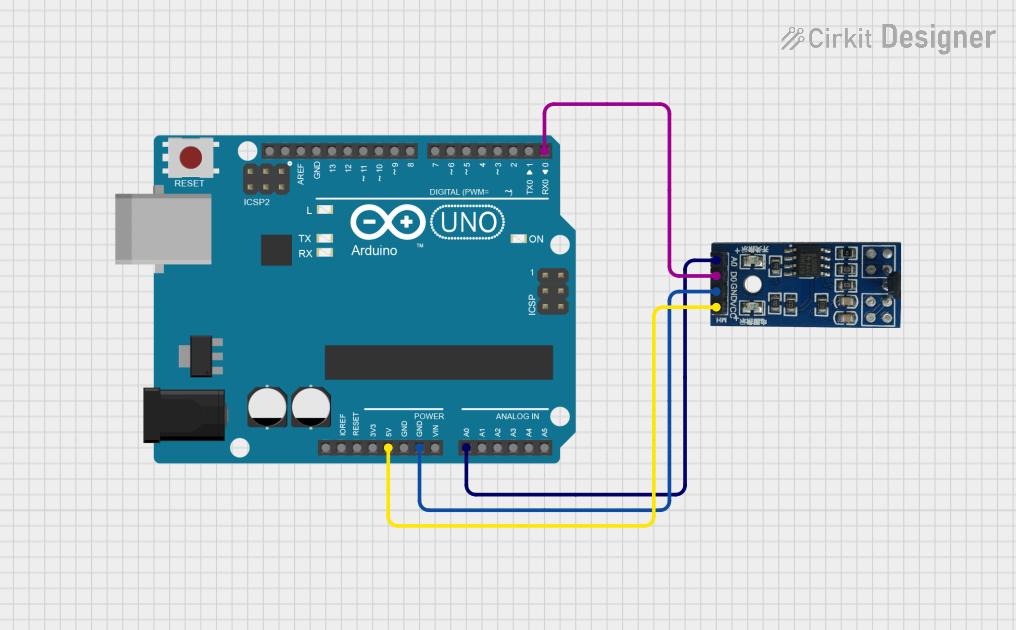
Example: Connecting GH1248 to an Arduino UNO

Circuit Diagram

Arduino UNO       GH1248 Hall Sensor
-----------       ------------------
5V --------------> Vcc
GND -------------> GND
Digital Pin 2 ---> OUT

Sample Code

// GH1248 Hall Sensor Example Code
// Connect the OUT pin of the GH1248 to digital pin 2 of the Arduino UNO

const int hallSensorPin = 2; // Hall sensor connected to digital pin 2
int sensorState = 0;         // Variable to store the sensor state

void setup() {
  pinMode(hallSensorPin, INPUT); // Set the hall sensor pin as input
  Serial.begin(9600);            // Initialize serial communication
}

void loop() {
  sensorState = digitalRead(hallSensorPin); // Read the sensor state

  if (sensorState == HIGH) {
    Serial.println("Magnetic field detected!"); // Print message if magnetic field is detected
  } else {
    Serial.println("No magnetic field.");       // Print message if no magnetic field is detected
  }

  delay(500); // Wait for 500 milliseconds before the next reading
}

Troubleshooting and FAQs

Common Issues and Solutions

  1. No Output Signal:

    • Check Connections: Ensure all connections are secure and correct.
    • Power Supply: Verify that the sensor is receiving the correct supply voltage.
    • Magnetic Field: Ensure the magnetic field is within the sensor's detection range.
  2. Unstable Readings:

    • Debouncing: Implement software debouncing to filter out noise.
    • Interference: Minimize electromagnetic interference from other components.
  3. Incorrect Readings:

    • Orientation: Ensure the magnetic field is perpendicular to the sensor.
    • Distance: Adjust the distance between the sensor and the magnetic source.

FAQs

Q1: Can the GH1248 Hall Sensor detect both North and South poles of a magnet? A1: Yes, the GH1248 can detect both North and South poles, but the output signal will be the same for both.

Q2: What is the maximum distance the GH1248 can detect a magnetic field? A2: The detection distance depends on the strength of the magnetic field. Typically, it can detect fields up to a few centimeters away.

Q3: Can I use the GH1248 Hall Sensor in an outdoor environment? A3: Yes, the GH1248 can operate in a wide temperature range (-40°C to 85°C), making it suitable for outdoor use. However, ensure it is protected from moisture and extreme conditions.

Q4: How do I know if the sensor is working correctly? A4: You can test the sensor by bringing a magnet close to it and observing the output signal. If the output changes from LOW to HIGH, the sensor is functioning correctly.

By following this documentation, users can effectively integrate the GH1248 Hall Sensor into their projects, ensuring accurate and reliable magnetic field detection.