How to Use Steering Wheel Controller: Examples, Pinouts, and Specs
Introduction
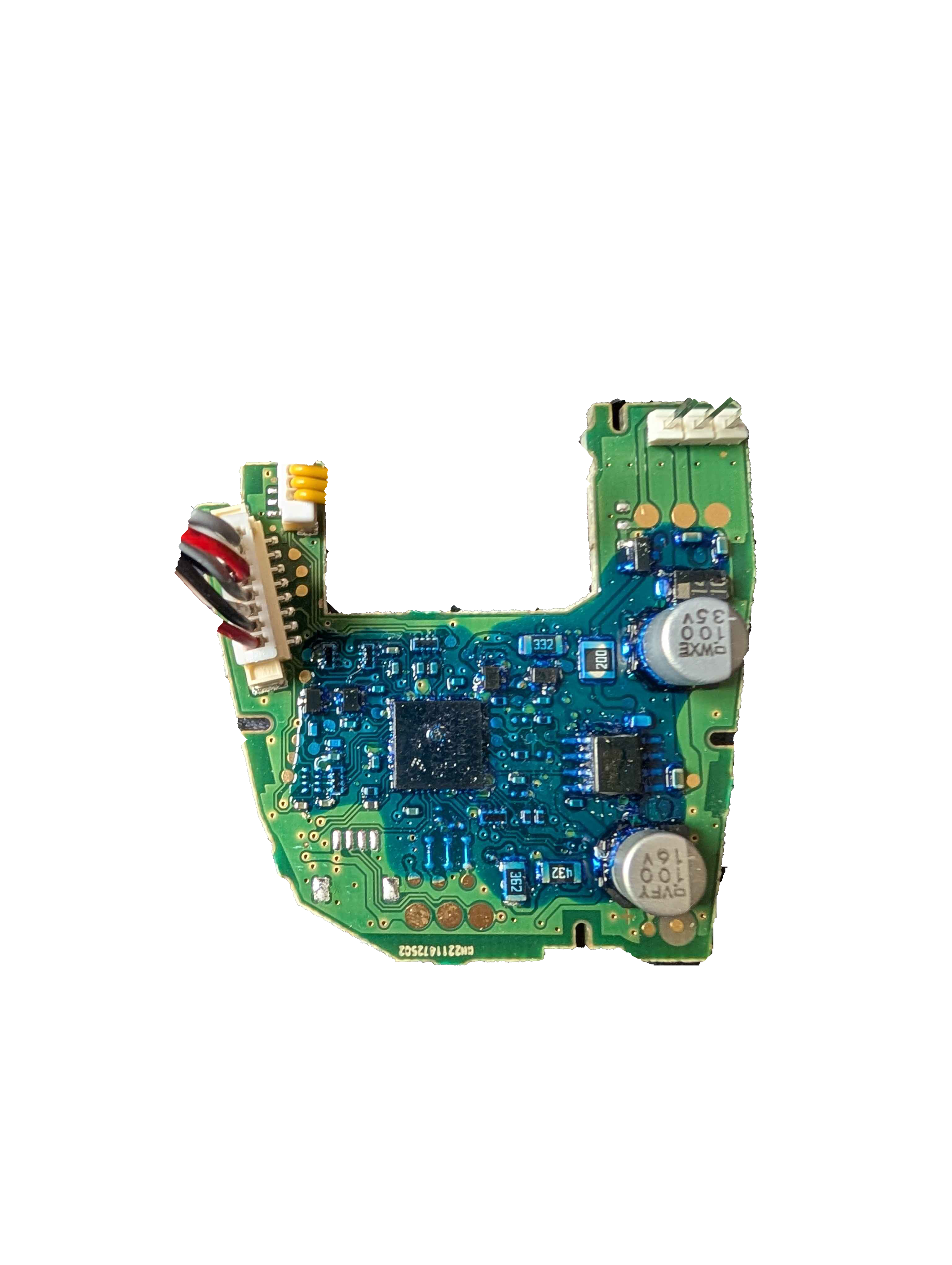
The ALPS ANS971218A Steering Wheel Controller is a versatile input device designed for controlling the steering of vehicles or simulations. It features a high-precision wheel that can be turned left or right, along with additional buttons and pedals for enhanced control. This component is widely used in automotive systems, gaming simulators, and training setups where accurate and responsive steering input is required.
Explore Projects Built with Steering Wheel Controller
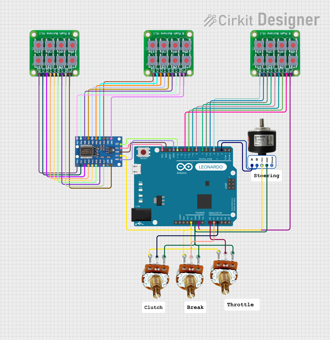
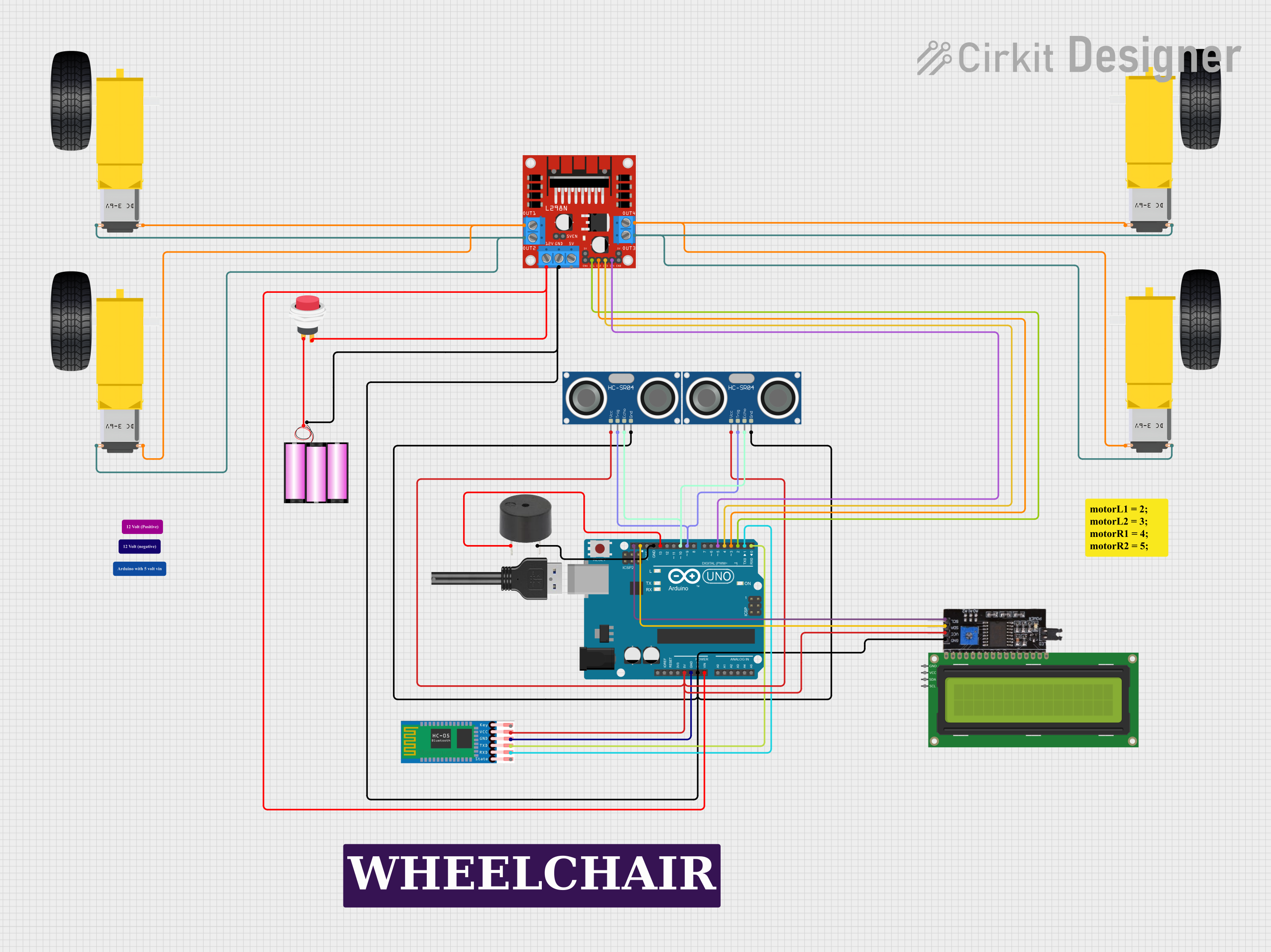

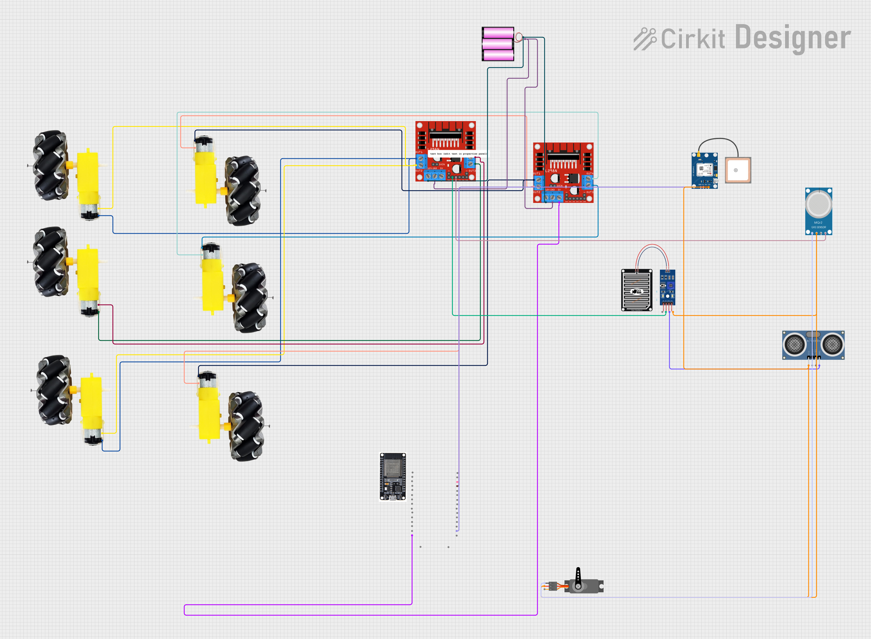
Explore Projects Built with Steering Wheel Controller
Common Applications and Use Cases
- Automotive steering systems for real-world vehicles
- Gaming simulators for racing and driving games
- Training simulators for driver education
- Robotics and remote-controlled vehicle steering
- Custom DIY projects requiring precise rotational input
Technical Specifications
The following table outlines the key technical details of the ALPS ANS971218A Steering Wheel Controller:
| Parameter | Value |
|---|---|
| Manufacturer | ALPS |
| Part ID | ANS971218A |
| Operating Voltage | 5V DC |
| Operating Current | 50mA (typical) |
| Interface | Analog and Digital (PWM, I2C) |
| Rotation Range | ±270° |
| Resolution | 12-bit (4096 steps) |
| Button Inputs | 8 configurable buttons |
| Pedal Inputs | 2 analog inputs (e.g., throttle, brake) |
| Operating Temperature | -10°C to 60°C |
| Dimensions | 300mm x 300mm x 150mm |
Pin Configuration and Descriptions
The ALPS ANS971218A Steering Wheel Controller has the following pin configuration:
| Pin Number | Pin Name | Description |
|---|---|---|
| 1 | VCC | Power supply input (5V DC) |
| 2 | GND | Ground |
| 3 | X_AXIS | Analog output for wheel rotation (±270° range) |
| 4 | BTN1 | Digital input/output for Button 1 |
| 5 | BTN2 | Digital input/output for Button 2 |
| 6 | BTN3 | Digital input/output for Button 3 |
| 7 | BTN4 | Digital input/output for Button 4 |
| 8 | PEDAL1 | Analog input for Pedal 1 (e.g., throttle) |
| 9 | PEDAL2 | Analog input for Pedal 2 (e.g., brake) |
| 10 | SDA | I2C Data Line |
| 11 | SCL | I2C Clock Line |
| 12 | PWM_OUT | PWM output for wheel position feedback |
Usage Instructions
How to Use the Component in a Circuit
- Power Supply: Connect the VCC pin to a 5V DC power source and the GND pin to ground.
- Wheel Rotation: Use the X_AXIS pin to read the analog voltage corresponding to the wheel's rotation angle. This can be connected to an ADC (Analog-to-Digital Converter) pin on a microcontroller.
- Buttons: Connect the button pins (BTN1 to BTN4) to digital input pins on your microcontroller. Configure pull-up or pull-down resistors as needed.
- Pedals: Connect the PEDAL1 and PEDAL2 pins to analog input pins on your microcontroller to read the pedal positions.
- I2C Communication: Use the SDA and SCL pins for I2C communication if you need to configure or read advanced settings.
- PWM Feedback: The PWM_OUT pin provides a pulse-width modulated signal representing the wheel's position. This can be used for feedback or control systems.
Important Considerations and Best Practices
- Ensure the power supply is stable and within the specified 5V range to avoid damage to the component.
- Use proper decoupling capacitors near the VCC pin to filter out noise.
- When using the I2C interface, ensure pull-up resistors (typically 4.7kΩ) are connected to the SDA and SCL lines.
- Avoid applying excessive force to the wheel or pedals to prevent mechanical damage.
- Calibrate the wheel and pedals in your software to ensure accurate readings.
Example Code for Arduino UNO
Below is an example code snippet to read the wheel's rotation and pedal positions using an Arduino UNO:
// Define analog input pins for the wheel and pedals
const int wheelPin = A0;  // X_AXIS pin connected to A0
const int pedal1Pin = A1; // PEDAL1 pin connected to A1
const int pedal2Pin = A2; // PEDAL2 pin connected to A2

void setup() {
  // Initialize serial communication for debugging
  Serial.begin(9600);
}

void loop() {
  // Read the analog values from the wheel and pedals
  int wheelValue = analogRead(wheelPin);  // Read wheel position
  int pedal1Value = analogRead(pedal1Pin); // Read throttle position
  int pedal2Value = analogRead(pedal2Pin); // Read brake position

  // Map the wheel value to a range of -270 to +270 degrees
  int wheelAngle = map(wheelValue, 0, 1023, -270, 270);

  // Print the values to the serial monitor
  Serial.print("Wheel Angle: ");
  Serial.print(wheelAngle);
  Serial.print("°, Pedal1: ");
  Serial.print(pedal1Value);
  Serial.print(", Pedal2: ");
  Serial.println(pedal2Value);

  // Add a small delay for stability
  delay(100);
}
Troubleshooting and FAQs
Common Issues and Solutions
No Output from the Wheel or Pedals
- Ensure the VCC and GND pins are properly connected.
- Verify that the analog pins on the microcontroller are functioning correctly.
- Check for loose or damaged wiring.
Inaccurate or Erratic Readings
- Ensure the power supply is stable and noise-free.
- Calibrate the wheel and pedals in your software to account for any offsets.
- Check for electromagnetic interference from nearby devices.
I2C Communication Not Working
- Verify that the SDA and SCL lines have proper pull-up resistors.
- Ensure the I2C address of the controller matches the address in your code.
- Check the wiring for continuity and proper connections.
Buttons Not Responding
- Confirm that the button pins are configured as digital inputs in your code.
- Use a multimeter to check if the buttons are functioning correctly.
FAQs
Q: Can this controller be used with Raspberry Pi?
A: Yes, the ALPS ANS971218A can be interfaced with a Raspberry Pi using its GPIO pins for analog and digital inputs, or via the I2C interface.
Q: How do I calibrate the wheel and pedals?
A: Calibration can be done in software by mapping the raw analog values to the desired range and adjusting for any offsets.
Q: Is the controller compatible with 3.3V systems?
A: The controller is designed for 5V operation. Use a level shifter if interfacing with a 3.3V system.
Q: Can I use this controller for robotics projects?
A: Absolutely! The precise rotational input and additional controls make it ideal for robotics and remote-controlled systems.