Cirkit Designer
Your all-in-one circuit design IDE
Home /
Component Documentation
How to Use CD4543B-FIAX: Examples, Pinouts, and Specs
Introduction
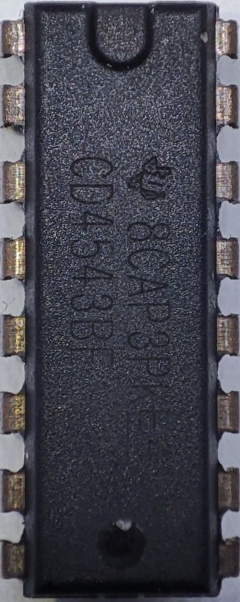
The CD4543B-FIAX is a versatile BCD-to-7-segment latch/decoder/driver integrated circuit (IC). It is designed to convert binary-coded decimal (BCD) inputs into control signals for 7-segment displays. This IC is commonly used in digital clocks, calculators, and other display devices where numerical data needs to be visually represented.
Explore Projects Built with CD4543B-FIAX
Satellite-Based Timing and Navigation System with SDR and Atomic Clock Synchronization

This circuit appears to be a complex system involving power supply management, GPS and timing synchronization, and data communication. It includes a SI-TEX G1 Satellite Compass for GPS data, an XHTF1021 Atomic Rubidium Clock for precise timing, and Ettus USRP B200 units for software-defined radio communication. Power is supplied through various SMPS units and distributed via terminal blocks and DC jacks. Data communication is facilitated by Beelink MINI S12 N95 computers, RS232 splitters, and a 1000BASE-T Media Converter for network connectivity. RF Directional Couplers are used to interface antennas with the USRP units, and the entire system is likely contained within cases for protection and organization.
Arduino UNO GSM Communication Hub with QR Code Reader and LCD Interface
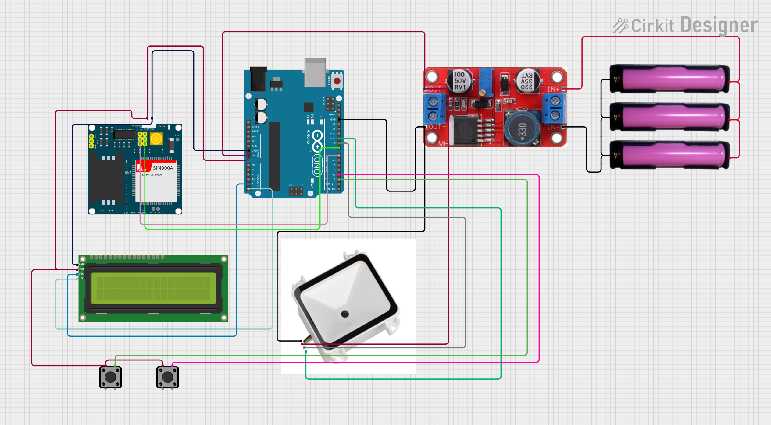
This circuit is designed to function as a communication and control system with cellular capabilities, QR code scanning, and display output. It is built around an Arduino UNO microcontroller, interfaced with a SIM900A module, a QR code reader, and an I2C LCD screen, powered by a series of 18650 batteries through a boost converter. Tactile switches provide user interaction, and the Arduino's embedded code controls the operation of the circuit.
Battery-Powered Emergency Alert System with NUCLEO-F072RB, SIM800L, and GPS NEO 6M

This circuit is an emergency alert system that uses a NUCLEO-F072RB microcontroller to send SMS alerts and make calls via a SIM800L GSM module, while obtaining location data from a GPS NEO 6M module. The system is powered by a Li-ion battery and includes a TP4056 module for battery charging and protection, with a rocker switch to control power to the microcontroller.
Arduino Mega 2560 Based Security System with Fingerprint Authentication and SMS Alerts

This circuit features an Arduino Mega 2560 microcontroller interfaced with a SIM800L GSM module, two fingerprint scanners, an I2C LCD display, an IR sensor, and a piezo buzzer. Power management is handled by a PowerBoost 1000 Basic Pad USB, a TP4056 charging module, and a Li-ion 18650 battery, with an option to use a Mini AC-DC 110V-230V to 5V 700mA module for direct power supply. The primary functionality appears to be a security system with GSM communication capabilities, biometric access control, and visual/audible feedback.
Explore Projects Built with CD4543B-FIAX
Satellite-Based Timing and Navigation System with SDR and Atomic Clock Synchronization
This circuit appears to be a complex system involving power supply management, GPS and timing synchronization, and data communication. It includes a SI-TEX G1 Satellite Compass for GPS data, an XHTF1021 Atomic Rubidium Clock for precise timing, and Ettus USRP B200 units for software-defined radio communication. Power is supplied through various SMPS units and distributed via terminal blocks and DC jacks. Data communication is facilitated by Beelink MINI S12 N95 computers, RS232 splitters, and a 1000BASE-T Media Converter for network connectivity. RF Directional Couplers are used to interface antennas with the USRP units, and the entire system is likely contained within cases for protection and organization.
Arduino UNO GSM Communication Hub with QR Code Reader and LCD Interface
This circuit is designed to function as a communication and control system with cellular capabilities, QR code scanning, and display output. It is built around an Arduino UNO microcontroller, interfaced with a SIM900A module, a QR code reader, and an I2C LCD screen, powered by a series of 18650 batteries through a boost converter. Tactile switches provide user interaction, and the Arduino's embedded code controls the operation of the circuit.
Battery-Powered Emergency Alert System with NUCLEO-F072RB, SIM800L, and GPS NEO 6M
This circuit is an emergency alert system that uses a NUCLEO-F072RB microcontroller to send SMS alerts and make calls via a SIM800L GSM module, while obtaining location data from a GPS NEO 6M module. The system is powered by a Li-ion battery and includes a TP4056 module for battery charging and protection, with a rocker switch to control power to the microcontroller.
Arduino Mega 2560 Based Security System with Fingerprint Authentication and SMS Alerts
This circuit features an Arduino Mega 2560 microcontroller interfaced with a SIM800L GSM module, two fingerprint scanners, an I2C LCD display, an IR sensor, and a piezo buzzer. Power management is handled by a PowerBoost 1000 Basic Pad USB, a TP4056 charging module, and a Li-ion 18650 battery, with an option to use a Mini AC-DC 110V-230V to 5V 700mA module for direct power supply. The primary functionality appears to be a security system with GSM communication capabilities, biometric access control, and visual/audible feedback.
Technical Specifications
Key Technical Details
| Parameter | Value |
|---|---|
| Supply Voltage | 3V to 15V |
| Input Voltage | 0V to VDD |
| Output Current | 25mA per segment |
| Power Dissipation | 500mW |
| Operating Temperature Range | -55°C to +125°C |
| Propagation Delay | 200ns (typical) |
Pin Configuration and Descriptions
| Pin No. | Pin Name | Description |
|---|---|---|
| 1 | A | BCD Input A |
| 2 | B | BCD Input B |
| 3 | C | BCD Input C |
| 4 | D | BCD Input D |
| 5 | LT | Lamp Test (active low) |
| 6 | BI/RBO | Blanking Input/Ripple Blanking Output (active low) |
| 7 | LE | Latch Enable (active high) |
| 8 | VSS | Ground (0V) |
| 9 | a | Segment a output |
| 10 | b | Segment b output |
| 11 | c | Segment c output |
| 12 | d | Segment d output |
| 13 | e | Segment e output |
| 14 | f | Segment f output |
| 15 | g | Segment g output |
| 16 | VDD | Supply Voltage |
Usage Instructions
How to Use the Component in a Circuit
- Power Supply: Connect pin 16 (VDD) to the positive supply voltage (3V to 15V) and pin 8 (VSS) to ground.
- BCD Inputs: Connect the BCD inputs (pins 1, 2, 3, and 4) to the binary-coded decimal signals.
- Latch Enable: Connect pin 7 (LE) to a control signal. When LE is high, the BCD input is latched.
- Lamp Test: Connect pin 5 (LT) to ground to test all segments of the display.
- Blanking Input: Connect pin 6 (BI/RBO) to ground to enable the display. When BI/RBO is high, all segments are turned off.
- Segment Outputs: Connect the segment outputs (pins 9 to 15) to the corresponding segments of the 7-segment display.
Important Considerations and Best Practices
- Ensure that the supply voltage does not exceed the maximum rating of 15V.
- Use current-limiting resistors for each segment output to prevent excessive current draw.
- Avoid floating inputs by connecting unused inputs to ground or VDD.
- For reliable operation, ensure that the latch enable (LE) signal is properly controlled.
Example Circuit with Arduino UNO
Below is an example of how to connect the CD4543B-FIAX to an Arduino UNO to drive a 7-segment display.
Circuit Diagram
Arduino UNO       CD4543B-FIAX       7-Segment Display
-----------       -------------       -----------------
  5V  ----------- V<sub>DD</sub> (16)
 GND  ----------- V<sub>SS</sub> (8)
 D2   ----------- A (1)
 D3   ----------- B (2)
 D4   ----------- C (3)
 D5   ----------- D (4)
 GND  ----------- LT (5)
 GND  ----------- BI/RBO (6)
 D6   ----------- LE (7)
                   a (9)  ----------- Segment a
                   b (10) ----------- Segment b
                   c (11) ----------- Segment c
                   d (12) ----------- Segment d
                   e (13) ----------- Segment e
                   f (14) ----------- Segment f
                   g (15) ----------- Segment g
Arduino Code
// Define pin connections
const int pinA = 2;
const int pinB = 3;
const int pinC = 4;
const int pinD = 5;
const int pinLE = 6;

void setup() {
  // Set pin modes
  pinMode(pinA, OUTPUT);
  pinMode(pinB, OUTPUT);
  pinMode(pinC, OUTPUT);
  pinMode(pinD, OUTPUT);
  pinMode(pinLE, OUTPUT);

  // Initialize latch enable to LOW
  digitalWrite(pinLE, LOW);
}

void loop() {
  // Example: Display the number 5
  displayNumber(5);
  delay(1000); // Wait for 1 second
}

void displayNumber(int num) {
  // Convert number to BCD
  int bcd[4];
  for (int i = 0; i < 4; i++) {
    bcd[i] = (num >> i) & 0x01;
  }

  // Set BCD inputs
  digitalWrite(pinA, bcd[0]);
  digitalWrite(pinB, bcd[1]);
  digitalWrite(pinC, bcd[2]);
  digitalWrite(pinD, bcd[3]);

  // Latch the inputs
  digitalWrite(pinLE, HIGH);
  delay(1); // Short delay to ensure latching
  digitalWrite(pinLE, LOW);
}
Troubleshooting and FAQs
Common Issues Users Might Face
No Display Output:
- Solution: Check the power supply connections and ensure that the supply voltage is within the specified range. Verify that the BCD inputs are correctly connected and that the latch enable (LE) signal is properly controlled.
Incorrect Segments Lighting Up:
- Solution: Verify the BCD input connections and ensure that the correct binary values are being sent to the inputs. Check for any loose or incorrect wiring.
All Segments Off:
- Solution: Ensure that the blanking input (BI/RBO) is connected to ground. If BI/RBO is high, all segments will be turned off.
Solutions and Tips for Troubleshooting
- Check Connections: Ensure that all connections are secure and correctly wired according to the circuit diagram.
- Verify Input Signals: Use a multimeter or oscilloscope to verify that the correct BCD input signals are being sent to the IC.
- Test with Known Good Components: If possible, test the circuit with known good components to isolate any faulty parts.
By following this documentation, users should be able to effectively utilize the CD4543B-FIAX BCD-to-7-segment latch/decoder/driver IC in their projects, ensuring accurate and reliable display of numerical data.