How to Use IMU: Examples, Pinouts, and Specs
Introduction
The Adafruit LSM9DS1 is a high-performance Inertial Measurement Unit (IMU) that integrates a 3-axis accelerometer, 3-axis gyroscope, and 3-axis magnetometer into a single compact package. This versatile sensor is capable of measuring linear acceleration, angular velocity, and magnetic field strength, making it ideal for applications requiring precise motion tracking and orientation sensing.
Explore Projects Built with IMU


Explore Projects Built with IMU
Common Applications and Use Cases
- Robotics and drone navigation
- Gesture recognition and motion tracking
- Virtual reality (VR) and augmented reality (AR) systems
- Wearable devices and fitness trackers
- Automotive systems for stability and navigation
Technical Specifications
The LSM9DS1 offers a wide range of features and capabilities, making it suitable for various applications. Below are the key technical details:
General Specifications
| Parameter | Value |
|---|---|
| Manufacturer | Adafruit |
| Part Number | LSM9DS1 |
| Operating Voltage | 2.4V to 3.6V |
| Communication Interface | I2C (up to 400 kHz) or SPI (up to 10 MHz) |
| Accelerometer Range | ±2g, ±4g, ±8g, ±16g |
| Gyroscope Range | ±245 dps, ±500 dps, ±2000 dps |
| Magnetometer Range | ±4 gauss, ±8 gauss, ±12 gauss, ±16 gauss |
| Operating Temperature | -40°C to +85°C |
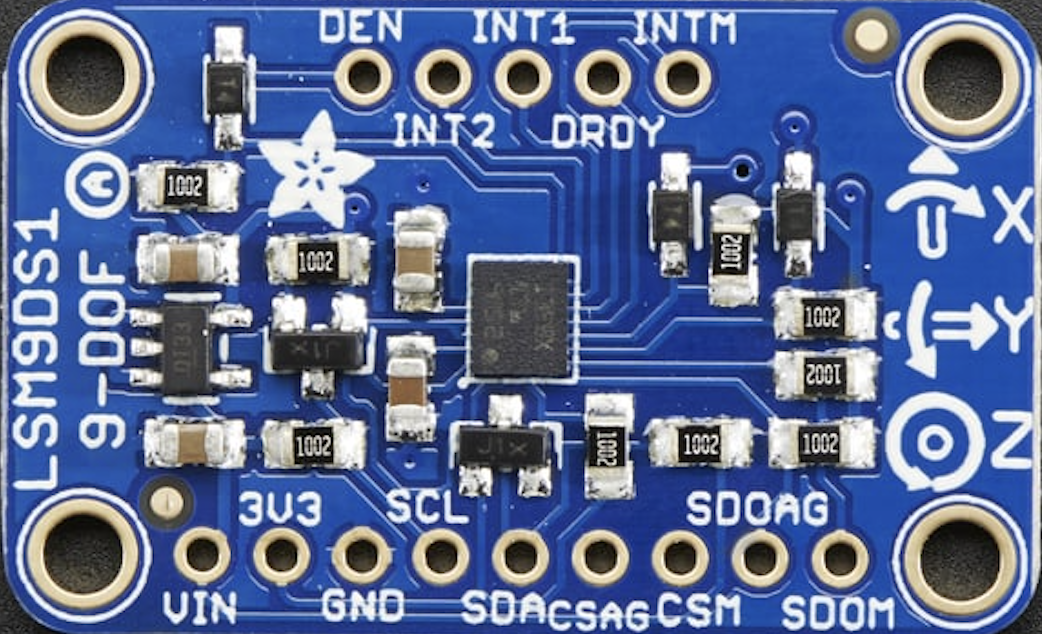
Pin Configuration
The LSM9DS1 breakout board from Adafruit features the following pin layout:
| Pin Name | Description |
|---|---|
| VIN | Power input (3.3V or 5V) |
| GND | Ground |
| SCL | I2C clock line (or SPI clock line in SPI mode) |
| SDA | I2C data line (or SPI MOSI line in SPI mode) |
| CSAG | Chip select for accelerometer and gyroscope (used in SPI mode) |
| CSM | Chip select for magnetometer (used in SPI mode) |
| SDOAG | Data output for accelerometer and gyroscope (used in SPI mode) |
| SDOM | Data output for magnetometer (used in SPI mode) |
| INT1 | Interrupt output 1 (configurable) |
| INT2 | Interrupt output 2 (configurable) |
Usage Instructions
The LSM9DS1 can be used in a variety of circuits and applications. Below are the steps to get started:
Connecting the LSM9DS1 to an Arduino UNO
Wiring: Connect the LSM9DS1 to the Arduino UNO as follows:
- VIN → 5V (or 3.3V if using a 3.3V Arduino)
- GND → GND
- SCL → A5 (I2C clock line on Arduino UNO)
- SDA → A4 (I2C data line on Arduino UNO)
Install Libraries: Download and install the Adafruit LSM9DS1 library from the Arduino Library Manager:
- Open the Arduino IDE.
- Go to
Sketch→Include Library→Manage Libraries. - Search for "Adafruit LSM9DS1" and click "Install".
Example Code: Use the following example code to read data from the LSM9DS1:
#include <Wire.h>
#include <Adafruit_Sensor.h>
#include <Adafruit_LSM9DS1.h>

// Create an instance of the LSM9DS1 sensor
Adafruit_LSM9DS1 lsm = Adafruit_LSM9DS1();

// Define I2C addresses for the sensor
#define LSM9DS1_XG_ADDRESS (0x6B) // Accelerometer and gyroscope address
#define LSM9DS1_M_ADDRESS  (0x1E) // Magnetometer address

void setup() {
  Serial.begin(115200);
  while (!Serial) {
    delay(10); // Wait for Serial to initialize
  }

  // Initialize the LSM9DS1 sensor
  if (!lsm.begin()) {
    Serial.println("Failed to initialize LSM9DS1. Check your wiring!");
    while (1);
  }
  Serial.println("LSM9DS1 initialized successfully!");

  // Set sensor ranges (optional)
  lsm.setupAccel(lsm.LSM9DS1_ACCELRANGE_2G); // Set accelerometer range to ±2g
  lsm.setupGyro(lsm.LSM9DS1_GYROSCALE_245DPS); // Set gyroscope range to ±245 dps
  lsm.setupMag(lsm.LSM9DS1_MAGGAIN_4GAUSS); // Set magnetometer range to ±4 gauss
}

void loop() {
  // Read accelerometer data
  sensors_event_t accel, gyro, mag, temp;
  lsm.getEvent(&accel, &gyro, &mag, &temp);

  // Print accelerometer data
  Serial.print("Accel X: "); Serial.print(accel.acceleration.x); Serial.print(" m/s^2 ");
  Serial.print("Y: "); Serial.print(accel.acceleration.y); Serial.print(" m/s^2 ");
  Serial.print("Z: "); Serial.print(accel.acceleration.z); Serial.println(" m/s^2");

  // Print gyroscope data
  Serial.print("Gyro X: "); Serial.print(gyro.gyro.x); Serial.print(" rad/s ");
  Serial.print("Y: "); Serial.print(gyro.gyro.y); Serial.print(" rad/s ");
  Serial.print("Z: "); Serial.print(gyro.gyro.z); Serial.println(" rad/s");

  // Print magnetometer data
  Serial.print("Mag X: "); Serial.print(mag.magnetic.x); Serial.print(" gauss ");
  Serial.print("Y: "); Serial.print(mag.magnetic.y); Serial.print(" gauss ");
  Serial.print("Z: "); Serial.print(mag.magnetic.z); Serial.println(" gauss");

  // Delay for readability
  delay(500);
}
Important Considerations and Best Practices
- Power Supply: Ensure the LSM9DS1 is powered within its operating voltage range (2.4V to 3.6V). If using a 5V microcontroller, the breakout board's onboard regulator will step down the voltage.
- I2C Pull-Up Resistors: The breakout board includes pull-up resistors for the I2C lines. If multiple I2C devices are connected, ensure the total pull-up resistance is appropriate.
- Sensor Calibration: For accurate measurements, calibrate the accelerometer, gyroscope, and magnetometer to account for offsets and environmental factors.
Troubleshooting and FAQs
Common Issues
Sensor Not Detected:
- Cause: Incorrect wiring or I2C address mismatch.
- Solution: Double-check the wiring and ensure the I2C addresses in the code match the sensor's default addresses.
Inaccurate Readings:
- Cause: Lack of calibration or environmental interference.
- Solution: Perform sensor calibration and ensure the sensor is placed away from magnetic or vibrational sources.
No Data Output:
- Cause: Serial monitor not initialized or incorrect baud rate.
- Solution: Ensure the Serial Monitor is set to the correct baud rate (115200 in the example).
FAQs
Q: Can the LSM9DS1 be used with a 5V microcontroller?
A: Yes, the Adafruit breakout board includes a voltage regulator and level shifters, allowing it to work with 5V systems.
Q: How do I switch between I2C and SPI communication?
A: By default, the breakout board uses I2C. To use SPI, connect the CSAG and CSM pins to the microcontroller and configure the library for SPI mode.
Q: What is the maximum sampling rate of the LSM9DS1?
A: The maximum output data rate (ODR) is 952 Hz for the accelerometer and gyroscope, and 80 Hz for the magnetometer.