Cirkit Designer
Your all-in-one circuit design IDE
Home /
Component Documentation
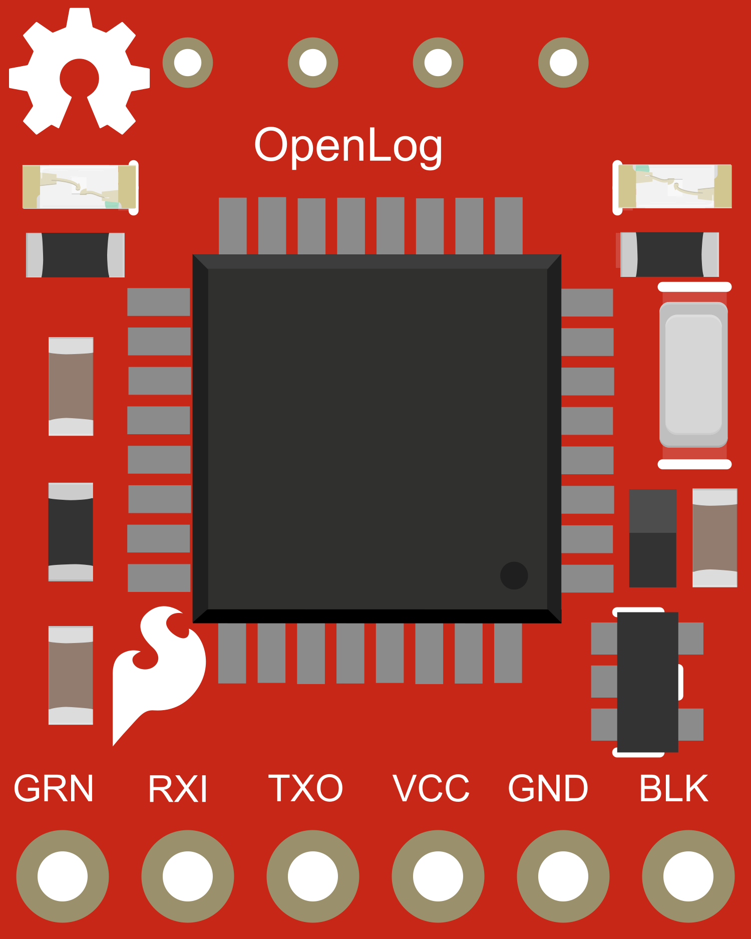
How to Use SparkFun OpenLog: Examples, Pinouts, and Specs
Introduction
The SparkFun OpenLog is an open-source data logger that works over a simple serial connection and supports microSD cards up to 32GB. It is designed to be a straightforward way to log data from sensors, serial devices, or any data source for that matter. The OpenLog provides a simple solution for adding storage to your project and can be used in applications such as weather stations, motion analysis, and event logging systems.
Explore Projects Built with SparkFun OpenLog
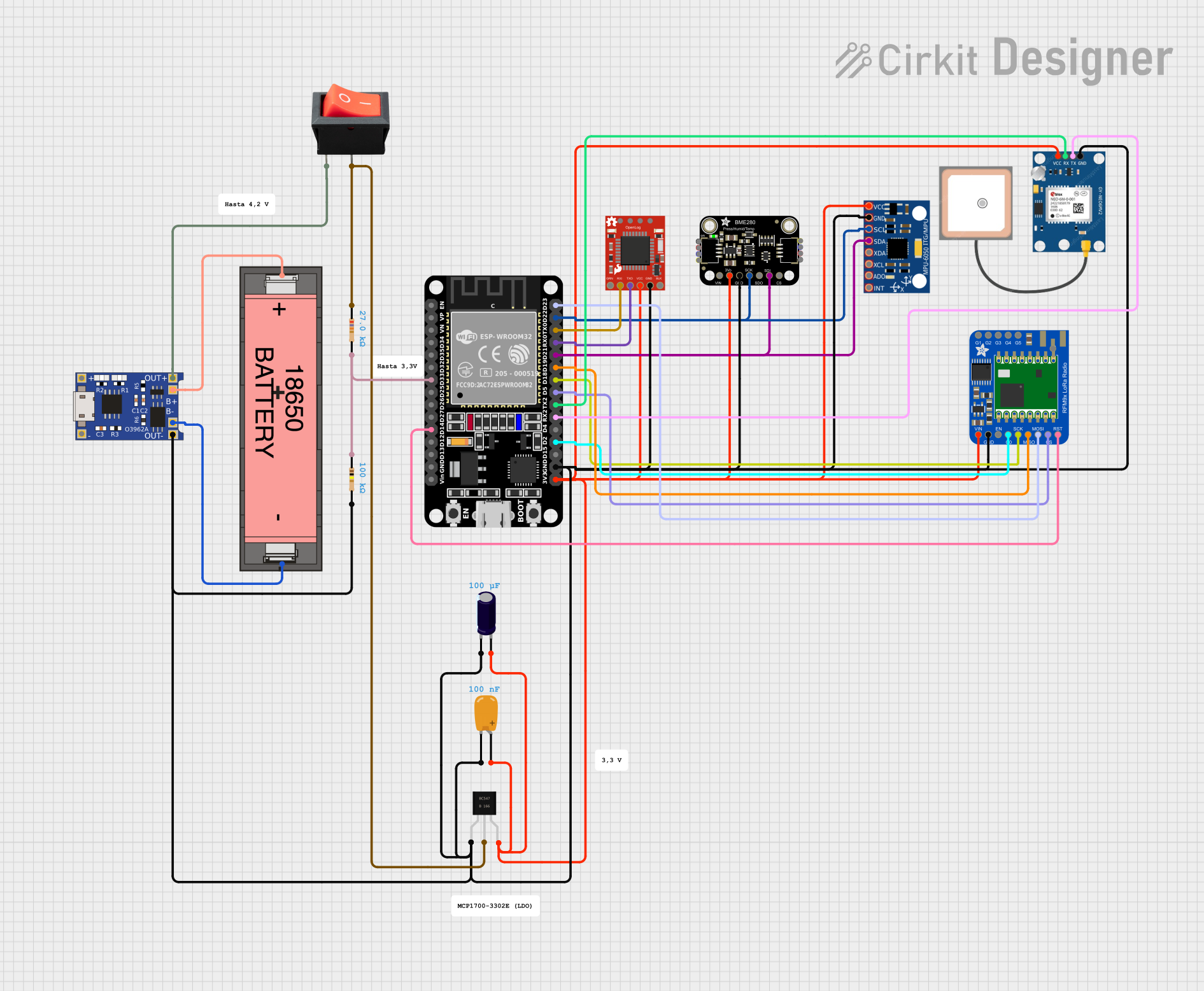
ESP32-Based Battery-Powered Environmental Monitoring System with LoRa and GPS

This circuit is a data logging and communication system powered by a Li-ion 18650 battery, featuring an ESP32 microcontroller. It includes sensors (BME280 and MPU-6050) for environmental and motion data, a GPS module for location tracking, and a LoRa radio for long-range communication. The SparkFun OpenLog module is used for data logging, and the TP4056 module manages battery charging.
ESP32-Based Battery-Powered Weather Station with LoRa and GPS
This circuit is a data logging and communication system powered by a Li-ion battery, featuring an ESP32 microcontroller. It includes sensors (BME280 and MPU-6050) for environmental and motion data, a GPS module for location tracking, and a LoRa radio for long-range communication. The system logs data to a SparkFun OpenLog and is managed by a TP4056 battery charger with power regulation components.
ESP32-Based GPS Tracker with Data Logging
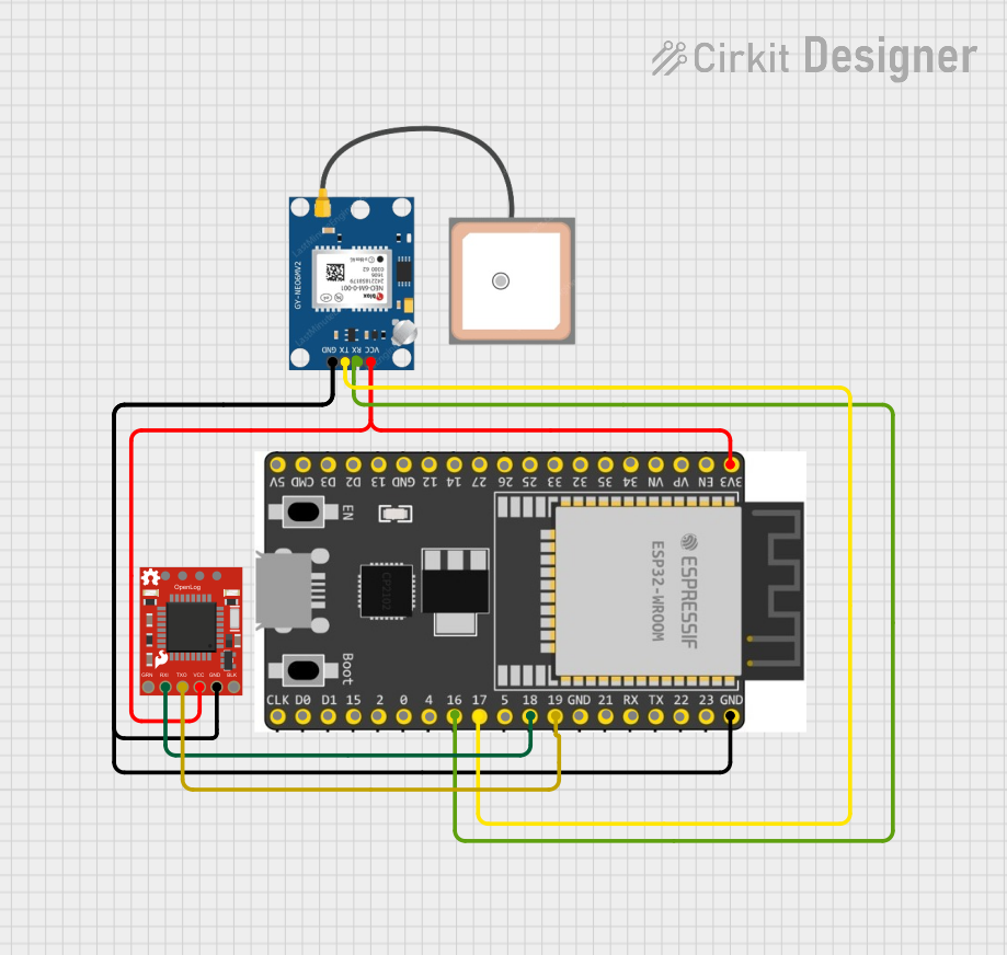
This circuit features an ESP32 Wroom Dev Kit microcontroller interfaced with a SparkFun OpenLog data logger and a GPS NEO 6M module. The ESP32 is configured to communicate with the OpenLog via serial connection (GPIO 18 and GPIO 19) and with the GPS module via another serial connection (GPIO 16 and GPIO 17). The purpose of this circuit is likely to log GPS data received from the GPS module onto the OpenLog for storage or later retrieval.
ESP32-Based Wi-Fi Weather Station with Data Logging
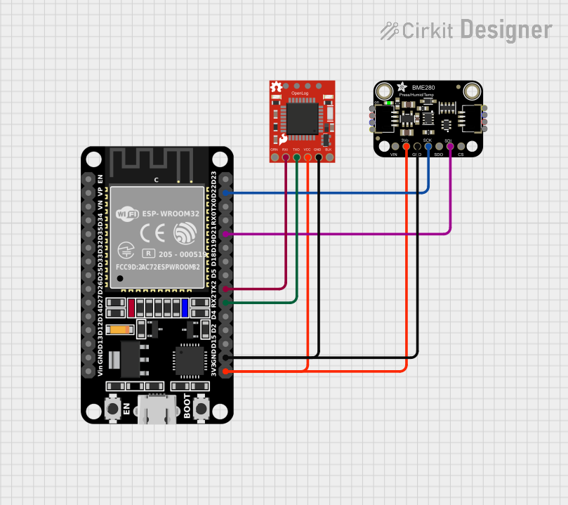
This circuit features an ESP32 microcontroller interfaced with an Adafruit BME280 sensor for environmental data acquisition and a SparkFun OpenLog for data logging. The ESP32 communicates with the BME280 via I2C and with the OpenLog via UART, while all components share common power and ground connections.
Explore Projects Built with SparkFun OpenLog
ESP32-Based Battery-Powered Environmental Monitoring System with LoRa and GPS
This circuit is a data logging and communication system powered by a Li-ion 18650 battery, featuring an ESP32 microcontroller. It includes sensors (BME280 and MPU-6050) for environmental and motion data, a GPS module for location tracking, and a LoRa radio for long-range communication. The SparkFun OpenLog module is used for data logging, and the TP4056 module manages battery charging.
ESP32-Based Battery-Powered Weather Station with LoRa and GPS
This circuit is a data logging and communication system powered by a Li-ion battery, featuring an ESP32 microcontroller. It includes sensors (BME280 and MPU-6050) for environmental and motion data, a GPS module for location tracking, and a LoRa radio for long-range communication. The system logs data to a SparkFun OpenLog and is managed by a TP4056 battery charger with power regulation components.
ESP32-Based GPS Tracker with Data Logging
This circuit features an ESP32 Wroom Dev Kit microcontroller interfaced with a SparkFun OpenLog data logger and a GPS NEO 6M module. The ESP32 is configured to communicate with the OpenLog via serial connection (GPIO 18 and GPIO 19) and with the GPS module via another serial connection (GPIO 16 and GPIO 17). The purpose of this circuit is likely to log GPS data received from the GPS module onto the OpenLog for storage or later retrieval.
ESP32-Based Wi-Fi Weather Station with Data Logging
This circuit features an ESP32 microcontroller interfaced with an Adafruit BME280 sensor for environmental data acquisition and a SparkFun OpenLog for data logging. The ESP32 communicates with the BME280 via I2C and with the OpenLog via UART, while all components share common power and ground connections.
Common Applications and Use Cases
- Data logging for experimental or environmental data
- Serial communication recording
- GPS logging
- Motion or event tracking in robotics
- Long-term data collection for analysis
Technical Specifications
Key Technical Details
- Voltage: 3.3V to 12V (regulated to 3.3V)
- Current: 2mA idle, 6mA at maximum recording rate
- Memory: microSD card (FAT16 or FAT32 format, up to 32GB)
- Communication: Serial UART at 9600 bps by default
- Baud Rates: 300 to 1000000 bps (configurable)
- Dimensions: 15mm x 25mm x 4mm
Pin Configuration and Descriptions
| Pin # | Name | Description |
|---|---|---|
| 1 | GND | Ground connection |
| 2 | VCC | Power supply (3.3V to 12V) |
| 3 | RXI | Serial Receive Input |
| 4 | TXO | Serial Transmit Output |
| 5 | GRN | A signal to indicate logging status (optional use) |
Usage Instructions
How to Use the Component in a Circuit
- Powering the OpenLog: Connect the VCC pin to a power supply between 3.3V and 12V, and connect the GND pin to the ground of your power supply.
- Connecting to a Microcontroller: Connect the RXI pin of the OpenLog to the TX (transmit) pin of your microcontroller, and the TXO pin to the RX (receive) pin if bidirectional communication is required.
- Inserting a microSD Card: Insert a formatted microSD card into the OpenLog's card slot.
- Configuring the Baud Rate: If necessary, configure the OpenLog to match the baud rate of your microcontroller by editing the
config.txtfile on the microSD card.
Important Considerations and Best Practices
- Ensure that the microSD card is formatted correctly before use.
- Avoid removing the microSD card or powering down the system while writing to prevent data corruption.
- For best performance, use a Class 10 microSD card.
- When connecting to a 5V system, ensure that the TXO pin is not directly connected to a 5V RX pin on the microcontroller to avoid damage.
Troubleshooting and FAQs
Common Issues Users Might Face
- Data not logging: Ensure the microSD card is properly inserted and formatted. Check the connections and confirm that the OpenLog is powered.
- Garbled data: Verify that the baud rate of the OpenLog matches the baud rate of the connected device.
- OpenLog not responding: Check the power supply and ensure that the voltage is within the specified range.
Solutions and Tips for Troubleshooting
- If the OpenLog is not creating new files, reformat the microSD card and check the
config.txtfile for proper settings. - For communication issues, use a serial monitor to confirm that the OpenLog is outputting the expected startup message.
- In case of file corruption, safely eject the microSD card from the OpenLog before removing it.
Example Code for Arduino UNO
#include <SoftwareSerial.h>

SoftwareSerial openLog(2, 3); // RX, TX

void setup() {
  // Start the serial communication
  Serial.begin(9600);
  openLog.begin(9600); // Match the OpenLog's default baud rate
  Serial.println("Initializing OpenLog");

  // Send a command to OpenLog to start a new log file
  openLog.print("new logFile.txt\r");
}

void loop() {
  // Example data to log
  String data = "Temperature: " + String(analogRead(A0));

  // Write data to the OpenLog
  openLog.println(data);

  // Wait for a second before logging next data point
  delay(1000);
}
Note: The above code assumes that the OpenLog is connected to digital pins 2 and 3 on the Arduino UNO. Adjust the SoftwareSerial pins in the code if you use different pins. Remember to keep the code comments concise and within the 80 character line length limit.