
How to Use LM2596 (TO263): Examples, Pinouts, and Specs
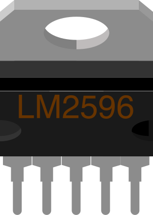
 Design with LM2596 (TO263) in Cirkit Designer
Introduction
The LM2596 is a step-down (buck) voltage regulator designed to efficiently convert a higher input voltage to a stable, lower output voltage. It is capable of delivering up to 3A of output current and operates with a wide input voltage range of 4.5V to 40V. The LM2596 is highly efficient, with typical efficiencies of up to 90%, making it ideal for power supply applications where heat dissipation and energy savings are critical. The TO263 package is optimized for surface mounting and provides excellent thermal performance.
Explore Projects Built with LM2596 (TO263)
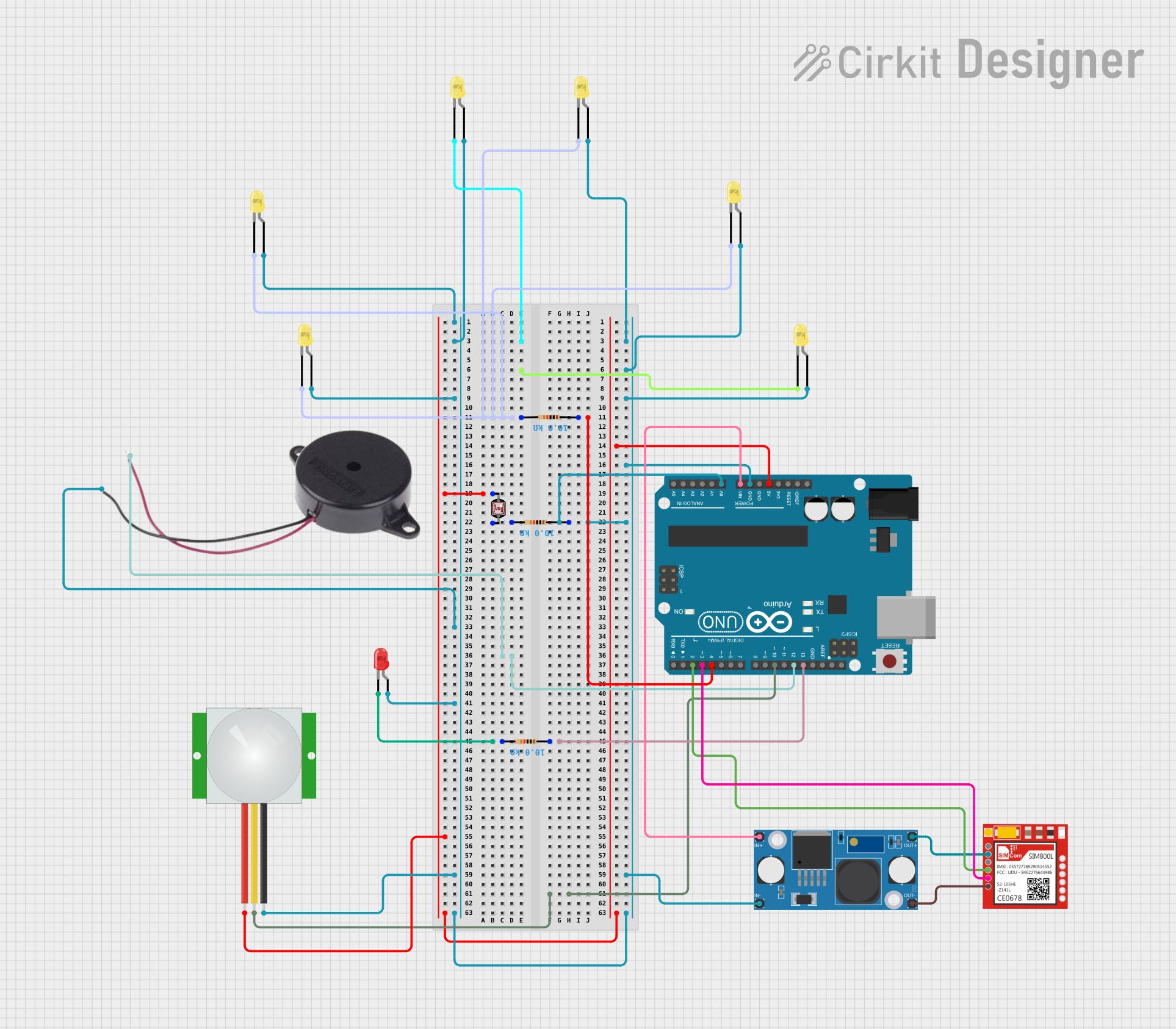 Open Project in Cirkit Designer
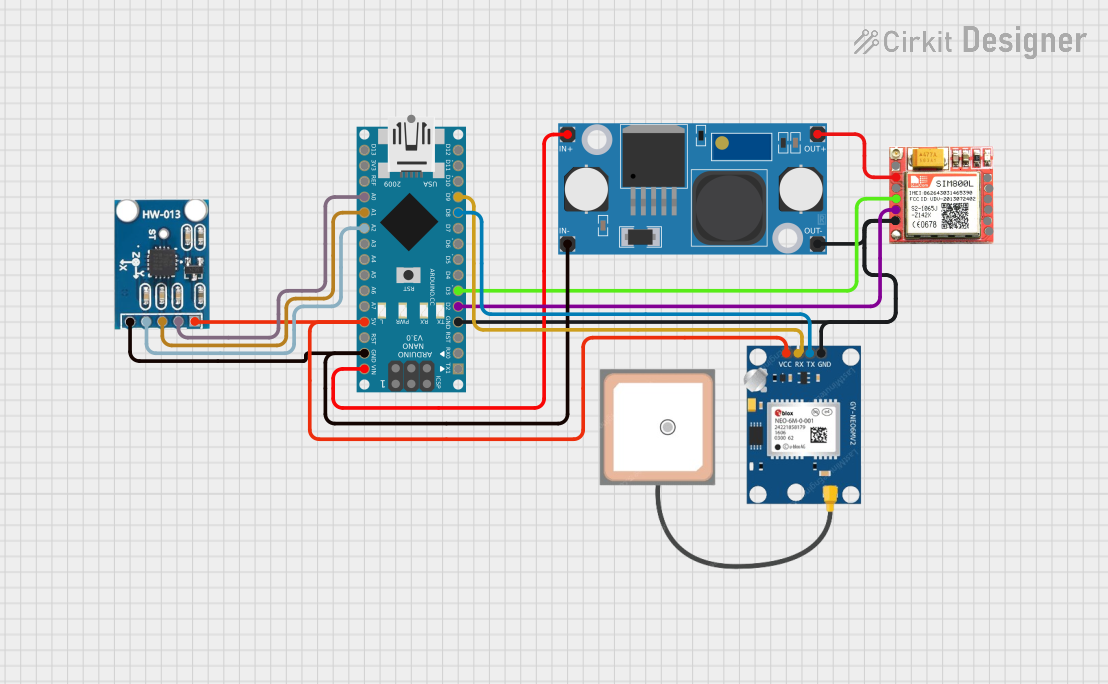 Open Project in Cirkit Designer
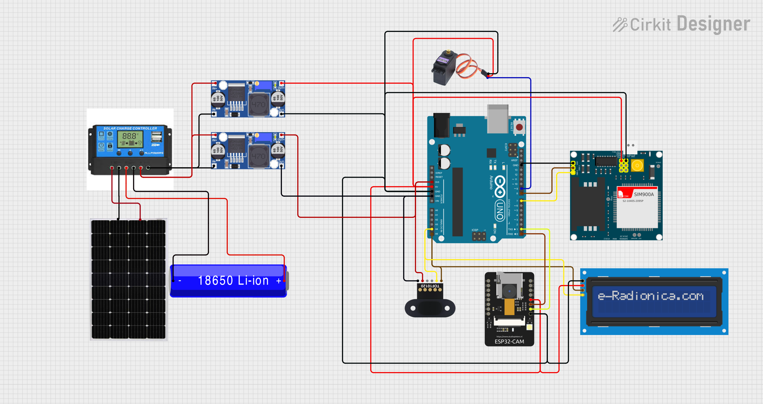 Open Project in Cirkit Designer
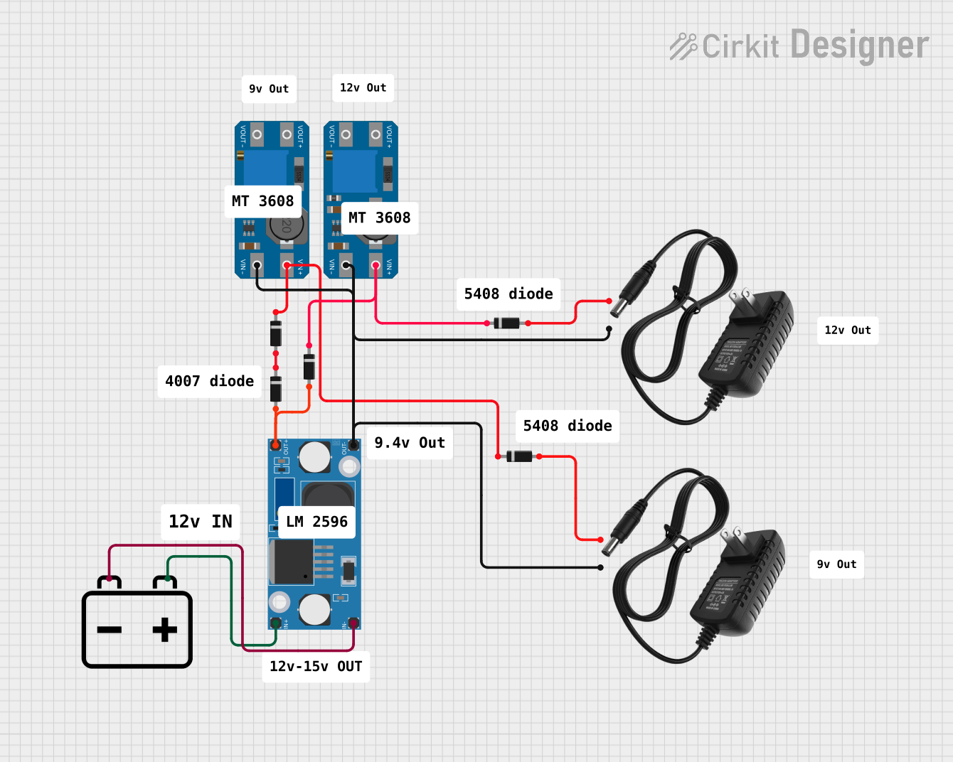 Open Project in Cirkit Designer
Explore Projects Built with LM2596 (TO263)
Open Project in Cirkit DesignerOpen Project in Cirkit DesignerOpen Project in Cirkit DesignerOpen Project in Cirkit DesignerCommon Applications
- DC-DC converters for battery-powered devices
- Adjustable power supplies
- Voltage regulation in embedded systems
- Industrial and automotive electronics
- LED drivers
Technical Specifications
Key Specifications
| Parameter | Value |
|---|---|
| Input Voltage Range | 4.5V to 40V |
| Output Voltage Range | 1.23V to 37V (adjustable) |
| Maximum Output Current | 3A |
| Efficiency | Up to 90% |
| Switching Frequency | 150 kHz (typical) |
| Output Voltage Tolerance | ±4% |
| Operating Temperature Range | -40°C to +125°C |
| Package Type | TO263 (surface-mount) |
Pin Configuration
The LM2596 in the TO263 package has 5 pins. The table below describes each pin:
| Pin Number | Pin Name | Description |
|---|---|---|
| 1 | VIN | Input voltage pin. Connect to the unregulated DC input voltage. |
| 2 | Output | Regulated output voltage pin. Connect to the load. |
| 3 | Ground | Ground pin. Connect to the system ground. |
| 4 | Feedback | Feedback pin. Used to set the output voltage via an external resistor divider. |
| 5 | ON/OFF | Enable pin. Logic high enables the regulator; logic low disables it. |
Usage Instructions
How to Use the LM2596 in a Circuit
- Input Voltage: Connect the input voltage (4.5V to 40V) to the VIN pin. Ensure the input voltage is higher than the desired output voltage by at least 3V for proper regulation.
- Output Voltage Adjustment: Use a resistor divider network connected to the Feedback pin to set the desired output voltage. The output voltage is calculated using the formula: [ V_{OUT} = V_{REF} \times \left(1 + \frac{R_2}{R_1}\right) ] where ( V_{REF} ) is 1.23V, ( R_1 ) is the resistor connected between the Feedback pin and ground, and ( R_2 ) is the resistor connected between the Feedback pin and the output.
- Output Capacitor: Place a low ESR capacitor (e.g., 220µF) at the output to ensure stability and reduce ripple.
- Input Capacitor: Add a capacitor (e.g., 100µF) at the input to filter noise and stabilize the input voltage.
- Inductor Selection: Choose an inductor with a current rating higher than the maximum output current and an appropriate inductance value to minimize ripple.
- Enable Pin: Connect the ON/OFF pin to VIN for continuous operation or use a microcontroller to toggle it for power-saving purposes.
Example Circuit
Below is a basic circuit diagram for using the LM2596 to step down 12V to 5V:
VIN (12V) ----[C1]----+----[LM2596]----+----[C2]---- VOUT (5V)
                      |                |            |
                     GND              GND          GND
- ( C1 ): Input capacitor (e.g., 100µF)
- ( C2 ): Output capacitor (e.g., 220µF)
Arduino Example Code
The LM2596 can be used with an Arduino to control the ON/OFF pin. Below is an example code snippet:
// Define the ON/OFF pin connected to the LM2596
const int lm2596EnablePin = 7;

void setup() {
  pinMode(lm2596EnablePin, OUTPUT); // Set the pin as an output
  digitalWrite(lm2596EnablePin, HIGH); // Enable the LM2596 regulator
}

void loop() {
  // Example: Toggle the LM2596 ON/OFF every 5 seconds
  digitalWrite(lm2596EnablePin, LOW); // Disable the regulator
  delay(5000); // Wait for 5 seconds
  digitalWrite(lm2596EnablePin, HIGH); // Enable the regulator
  delay(5000); // Wait for 5 seconds
}
Best Practices
- Use low ESR capacitors for input and output filtering to minimize noise and ripple.
- Ensure proper heat dissipation by using a heatsink or adequate PCB thermal design.
- Avoid exceeding the maximum input voltage (40V) or output current (3A) to prevent damage.
- Use shielded inductors to reduce electromagnetic interference (EMI).
Troubleshooting and FAQs
Common Issues and Solutions
Output Voltage is Incorrect
- Verify the resistor divider network connected to the Feedback pin.
- Check for loose connections or damaged components.
Excessive Heat
- Ensure the input voltage is within the specified range.
- Use a heatsink or improve PCB thermal dissipation.
High Output Ripple
- Use low ESR capacitors at the input and output.
- Verify the inductor value and ensure it meets the design requirements.
Regulator Not Turning On
- Check the ON/OFF pin voltage. Ensure it is pulled high to enable the regulator.
- Verify the input voltage is above the minimum required (4.5V).
FAQs
Q: Can the LM2596 be used for negative voltage regulation?
A: No, the LM2596 is designed for positive voltage regulation only.
Q: What is the maximum efficiency of the LM2596?
A: The LM2596 can achieve efficiencies of up to 90%, depending on the input/output voltage and load conditions.
Q: Can I use the LM2596 without an external inductor?
A: No, an external inductor is required for proper operation as it is a switching regulator.
Q: How do I calculate the inductor value?
A: The inductor value depends on the input voltage, output voltage, switching frequency, and load current. Use the formula provided in the LM2596 datasheet for precise calculations.