Cirkit Designer Logo
Cirkit Designer
Your all-in-one circuit design IDE
Home / 
Component Documentation

How to Use THAT_1646_Breakout: Examples, Pinouts, and Specs

Image of THAT_1646_Breakout
Cirkit Designer LogoDesign with THAT_1646_Breakout in Cirkit Designer

Introduction

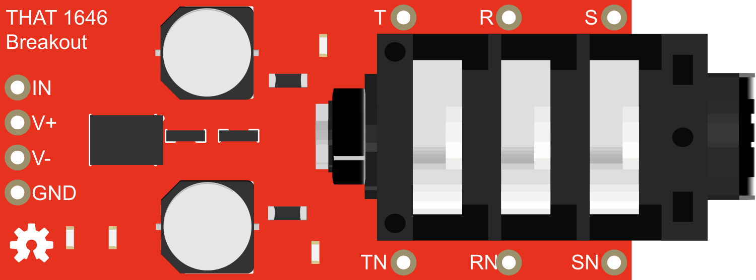
The THAT 1646 Breakout is a specialized module designed for audio enthusiasts and professionals who require high-quality signal transmission. The breakout board simplifies the use of the THAT 1646 integrated circuit, a renowned low-noise balanced line driver known for its exceptional performance in audio applications. This component is ideal for integrating into professional audio equipment, mixers, and recording interfaces where maintaining signal integrity is crucial.

Explore Projects Built with THAT_1646_Breakout

Use Cirkit Designer to design, explore, and prototype these projects online. Some projects support real-time simulation. Click "Open Project" to start designing instantly!
Battery-Powered Arduino UNO and ESP-8266 Smart Controller with LCD and RTC
Image of Ogie Diagram: A project utilizing THAT_1646_Breakout in a practical application
This circuit is a power management and control system that uses a 12V power supply and a 18650 Li-ion battery pack to provide a stable 5V output through a step-down buck converter. It includes an Arduino UNO, an ESP-8266 controller, a DS1307 RTC module, and a 20x4 I2C LCD display for monitoring and control purposes. The ULN2003A breakout board is used for driving higher current loads.
Cirkit Designer LogoOpen Project in Cirkit Designer
Arduino Mega 2560-Based Real-Time Clock and Data Logging System with OLED Display
Image of projectwiring: A project utilizing THAT_1646_Breakout in a practical application
This circuit features an Arduino Mega 2560 microcontroller interfaced with an OLED display, a DS1307 RTC module, a microSD card breakout, a pushbutton, and a blue LED. The Arduino handles data logging to the microSD card, displays information on the OLED, and reads real-time data from the RTC module, while the pushbutton and LED provide user interaction and status indication.
Cirkit Designer LogoOpen Project in Cirkit Designer
Raspberry Pi 3B Powered 15.6-inch Touchscreen Display with USB Type-C Power Delivery
Image of Pi Touch Screen Kiosk: A project utilizing THAT_1646_Breakout in a practical application
This circuit powers a 15.6-inch capacitive touch display and a Raspberry Pi 3B using a USB Type C power delivery breakout and two buck converters. The Raspberry Pi connects to the display via HDMI and USB for touch functionality, while the power delivery breakout provides regulated power to both the display and the Raspberry Pi through the buck converters.
Cirkit Designer LogoOpen Project in Cirkit Designer
8-Channel Multiplexer with Pushbutton Inputs and Resistor Network
Image of 8 push pull buttons one mux: A project utilizing THAT_1646_Breakout in a practical application
This circuit uses a SparkFun 74HC4051 8-Channel Multiplexer to read the states of eight pushbuttons. Each pushbutton is connected to a corresponding input channel on the multiplexer through a 2k Ohm resistor, allowing the multiplexer to sequentially read the button states and output them to a single data line.
Cirkit Designer LogoOpen Project in Cirkit Designer

Explore Projects Built with THAT_1646_Breakout

Use Cirkit Designer to design, explore, and prototype these projects online. Some projects support real-time simulation. Click "Open Project" to start designing instantly!
Image of Ogie Diagram: A project utilizing THAT_1646_Breakout in a practical application
Battery-Powered Arduino UNO and ESP-8266 Smart Controller with LCD and RTC
This circuit is a power management and control system that uses a 12V power supply and a 18650 Li-ion battery pack to provide a stable 5V output through a step-down buck converter. It includes an Arduino UNO, an ESP-8266 controller, a DS1307 RTC module, and a 20x4 I2C LCD display for monitoring and control purposes. The ULN2003A breakout board is used for driving higher current loads.
Cirkit Designer LogoOpen Project in Cirkit Designer
Image of projectwiring: A project utilizing THAT_1646_Breakout in a practical application
Arduino Mega 2560-Based Real-Time Clock and Data Logging System with OLED Display
This circuit features an Arduino Mega 2560 microcontroller interfaced with an OLED display, a DS1307 RTC module, a microSD card breakout, a pushbutton, and a blue LED. The Arduino handles data logging to the microSD card, displays information on the OLED, and reads real-time data from the RTC module, while the pushbutton and LED provide user interaction and status indication.
Cirkit Designer LogoOpen Project in Cirkit Designer
Image of Pi Touch Screen Kiosk: A project utilizing THAT_1646_Breakout in a practical application
Raspberry Pi 3B Powered 15.6-inch Touchscreen Display with USB Type-C Power Delivery
This circuit powers a 15.6-inch capacitive touch display and a Raspberry Pi 3B using a USB Type C power delivery breakout and two buck converters. The Raspberry Pi connects to the display via HDMI and USB for touch functionality, while the power delivery breakout provides regulated power to both the display and the Raspberry Pi through the buck converters.
Cirkit Designer LogoOpen Project in Cirkit Designer
Image of 8 push pull buttons one mux: A project utilizing THAT_1646_Breakout in a practical application
8-Channel Multiplexer with Pushbutton Inputs and Resistor Network
This circuit uses a SparkFun 74HC4051 8-Channel Multiplexer to read the states of eight pushbuttons. Each pushbutton is connected to a corresponding input channel on the multiplexer through a 2k Ohm resistor, allowing the multiplexer to sequentially read the button states and output them to a single data line.
Cirkit Designer LogoOpen Project in Cirkit Designer

Common Applications and Use Cases

  • Professional audio mixing consoles
  • Studio recording equipment
  • Audio interfaces
  • Balanced audio signal transmission lines
  • High-fidelity home audio systems

Technical Specifications

Key Technical Details

  • Supply Voltage (V+ to V-): ±4V to ±18V
  • Output Offset Voltage: ±4mV (max)
  • Output Noise (22Hz to 22kHz): -108dBu
  • Total Harmonic Distortion (THD+N): 0.0005% at 1kHz
  • Maximum Output Level: +27dBu into 600Ω
  • Slew Rate: 15V/µs
  • Quiescent Current: 8.5mA per channel

Pin Configuration and Descriptions

Pin Number Name Description
1 OUT+ Positive output signal
2 V- Negative supply voltage
3 IN- Inverting input signal
4 IN+ Non-inverting input signal
5 V+ Positive supply voltage
6 OUT- Negative output signal

Usage Instructions

How to Use the Component in a Circuit

  1. Power Supply: Connect the V+ and V- pins to a bipolar power supply within the specified voltage range.
  2. Input Signal: Apply the audio signal to the IN+ and IN- pins. For single-ended signals, connect the IN- to the ground.
  3. Output Signal: Connect the OUT+ and OUT- pins to the receiving device, ensuring it is capable of accepting balanced signals.
  4. Grounding: Ensure proper grounding in the audio system to minimize noise and interference.

Important Considerations and Best Practices

  • Use decoupling capacitors close to the V+ and V- pins to stabilize the power supply.
  • Keep signal paths short and use shielded cables to reduce the risk of noise pickup.
  • Avoid running audio signal lines near high-current power lines.
  • Ensure that the power supply is well-regulated and free from noise.
  • Use proper impedance matching to maximize signal integrity and minimize reflections.

Troubleshooting and FAQs

Common Issues Users Might Face

  • Distortion or Clipping: Ensure that the input signal level does not exceed the maximum input level of the THAT 1646.
  • Increased Noise: Check for proper grounding and use shielded cables. Ensure that the power supply is clean and stable.
  • No Output Signal: Verify that the power supply is connected correctly and within the specified range. Check the input signal and connections.

Solutions and Tips for Troubleshooting

  • If you encounter noise, re-check the grounding scheme and cable quality.
  • For distortion issues, reduce the input signal level or check for proper power supply voltages.
  • In case of no output, ensure that the IC is not damaged and that all connections are secure.

Example Code for Arduino UNO

Below is an example code snippet for interfacing the THAT 1646 Breakout with an Arduino UNO for basic testing purposes. This code generates a simple test tone.

// Define the pin connected to the DAC or PWM output
const int audioOutPin = 9; // Use a PWM pin

void setup() {
  // Set the audio output pin as an output
  pinMode(audioOutPin, OUTPUT);
}

void loop() {
  // Generate a 1kHz test tone using PWM
  // Note: This is a simple approximation and not a pure tone.
  for (int i = 0; i < 255; i++) {
    analogWrite(audioOutPin, i);
    delayMicroseconds(500); // 1kHz tone
  }
  for (int i = 255; i >= 0; i--) {
    analogWrite(audioOutPin, i);
    delayMicroseconds(500); // 1kHz tone
  }
}

Note: The above code is a basic example to demonstrate signal generation. The Arduino's PWM output is not a substitute for a true DAC and will not produce a high-fidelity audio signal. For testing the THAT 1646 Breakout, a proper audio source should be used.

This documentation provides an overview of the THAT 1646 Breakout board, its technical specifications, usage instructions, and troubleshooting tips. For further assistance or technical support, please contact the manufacturer or visit the online community forums dedicated to audio electronics.