How to Use LM7805 blank board: Examples, Pinouts, and Specs
Introduction
The LM7805 blank board is a compact voltage regulator module designed to provide a stable 5V DC output from a higher input voltage. It is based on the LM7805 linear voltage regulator IC, which is widely used for powering low-voltage electronic circuits. The blank board version integrates the LM7805 IC with essential components like input/output capacitors and a PCB for easy integration into projects.
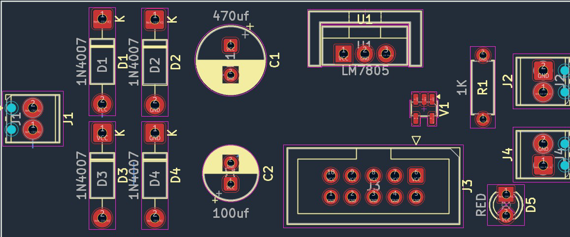
Explore Projects Built with LM7805 blank board

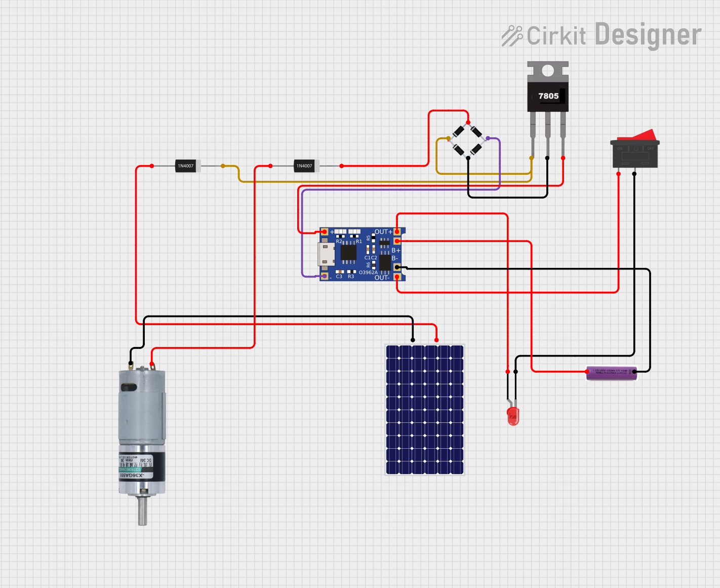


Explore Projects Built with LM7805 blank board
Common Applications and Use Cases
- Powering microcontrollers (e.g., Arduino, ESP32, Raspberry Pi peripherals)
- Regulating voltage for sensors and modules
- Prototyping and breadboard-friendly power supply
- Converting 9V or 12V DC to 5V for USB-powered devices
Technical Specifications
Key Technical Details
- Input Voltage Range: 7V to 25V DC
- Output Voltage: 5V DC (regulated)
- Maximum Output Current: 1A (with proper heat dissipation)
- Quiescent Current: ~5mA
- Thermal Shutdown Protection: Yes
- Short-Circuit Protection: Yes
- Operating Temperature Range: -40°C to +125°C
Pin Configuration and Descriptions
The LM7805 blank board typically has three pins or terminals for easy connection:
| Pin | Name | Description |
|---|---|---|
| 1 | Input (VIN) | Connect to the unregulated DC input voltage (7V to 25V). |
| 2 | Ground (GND) | Common ground for input and output. |
| 3 | Output (VOUT) | Provides a regulated 5V DC output. |
Usage Instructions
How to Use the LM7805 Blank Board in a Circuit
Connect the Input Voltage:
- Attach the positive terminal of your DC power source (7V to 25V) to the
VINpin. - Connect the negative terminal of the power source to the
GNDpin.
- Attach the positive terminal of your DC power source (7V to 25V) to the
Connect the Output Load:
- Connect the device or circuit requiring 5V to the
VOUTpin. - Ensure the ground of the load is connected to the
GNDpin.
- Connect the device or circuit requiring 5V to the
Verify Connections:
- Double-check all connections to avoid reverse polarity or short circuits.
Power On:
- Turn on the input power source. The board will regulate the input voltage and provide a stable 5V output.
Important Considerations and Best Practices
Heat Dissipation:
The LM7805 IC can get hot under high current loads. Use a heatsink or ensure proper ventilation if the current exceeds 500mA.Input Voltage:
Ensure the input voltage is at least 2V higher than the output voltage (minimum 7V for a 5V output). Avoid exceeding 25V to prevent damage.Capacitors:
The blank board typically includes input and output capacitors for stability. If not, add a 0.33µF capacitor on the input and a 0.1µF capacitor on the output.Arduino UNO Example:
The LM7805 blank board can be used to power an Arduino UNO. Connect theVOUTpin to the Arduino's 5V pin andGNDto the Arduino's GND pin.
Example Code for Arduino UNO
// Example: Blink an LED using Arduino UNO powered by LM7805 blank board

const int ledPin = 13; // Pin connected to the onboard LED

void setup() {
  pinMode(ledPin, OUTPUT); // Set the LED pin as an output
}

void loop() {
  digitalWrite(ledPin, HIGH); // Turn the LED on
  delay(1000);               // Wait for 1 second
  digitalWrite(ledPin, LOW);  // Turn the LED off
  delay(1000);               // Wait for 1 second
}
Troubleshooting and FAQs
Common Issues and Solutions
No Output Voltage:
- Cause: Incorrect wiring or insufficient input voltage.
- Solution: Verify the input voltage is within the 7V to 25V range and check all connections.
Overheating:
- Cause: High current draw or insufficient heat dissipation.
- Solution: Add a heatsink to the LM7805 IC or reduce the load current.
Output Voltage Not Stable:
- Cause: Missing or inadequate capacitors.
- Solution: Add a 0.33µF capacitor on the input and a 0.1µF capacitor on the output.
Short Circuit Protection Triggered:
- Cause: Output terminals are shorted.
- Solution: Disconnect the power, fix the short circuit, and reconnect.
FAQs
Can I use the LM7805 blank board with a 6V input?
No, the input voltage must be at least 7V for proper regulation.What is the maximum current the LM7805 blank board can provide?
The board can provide up to 1A, but proper heat dissipation is required for currents above 500mA.Can I use the LM7805 blank board to power a USB device?
Yes, as long as the device requires 5V and the current draw does not exceed 1A.Is the LM7805 blank board suitable for battery-powered projects?
It depends on the battery voltage. Ensure the battery provides at least 7V for proper regulation.