How to Use ESP32-C6-DevKit1: Examples, Pinouts, and Specs
Introduction
The ESP32-C6-DevKit1, manufactured by Espressif, is a development board built around the ESP32-C6 chip. This board integrates Wi-Fi 6, Bluetooth 5 (LE), and 802.15.4 (Thread/Zigbee) capabilities, making it an ideal choice for IoT applications. It provides a versatile platform for prototyping and development, featuring multiple GPIO pins, ADCs, and support for various communication protocols.
Explore Projects Built with ESP32-C6-DevKit1

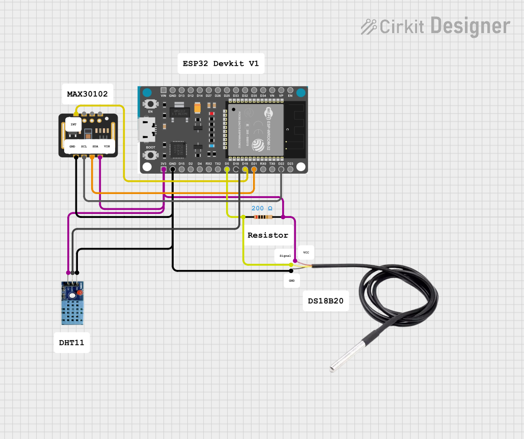


Explore Projects Built with ESP32-C6-DevKit1
Common Applications
- Smart home devices (e.g., lighting, thermostats, security systems)
- Industrial IoT (e.g., sensors, actuators, monitoring systems)
- Wearable devices
- Wireless communication hubs (e.g., Zigbee/Thread gateways)
- Low-power, high-performance IoT solutions
Technical Specifications
The ESP32-C6-DevKit1 is designed to provide robust performance for IoT applications. Below are its key technical details:
Key Features
- Processor: 32-bit RISC-V single-core processor, up to 160 MHz
- Wireless Connectivity:
- Wi-Fi 6 (802.11ax) with 20 MHz bandwidth
- Bluetooth 5 (LE) with long-range support
- IEEE 802.15.4 (Thread/Zigbee)
- Memory:
- 320 KB SRAM
- 384 KB ROM
- External flash support via SPI
- GPIO: 22 programmable GPIO pins
- ADC: 12-bit ADC with up to 5 channels
- Operating Voltage: 3.3V
- Power Supply: USB or external 5V
- Interfaces:
- SPI, I2C, I2S, UART, PWM
- JTAG debugging support
- Dimensions: 52 mm x 25 mm
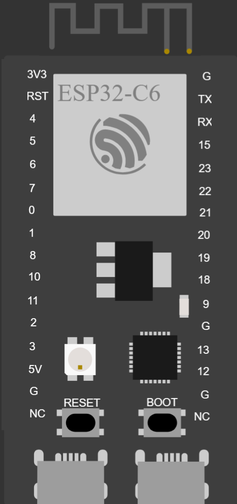
Pin Configuration
The ESP32-C6-DevKit1 features a 2-row pin header layout. Below is the pin configuration:
| Pin | Name | Function | Notes |
|---|---|---|---|
| 1 | 3V3 | Power Supply | 3.3V output |
| 2 | GND | Ground | Common ground |
| 3 | GPIO0 | General Purpose I/O | Boot mode selection |
| 4 | GPIO1 | General Purpose I/O | UART TX |
| 5 | GPIO2 | General Purpose I/O | ADC channel 1 |
| 6 | GPIO3 | General Purpose I/O | UART RX |
| 7 | GPIO4 | General Purpose I/O | ADC channel 2 |
| 8 | GPIO5 | General Purpose I/O | PWM output |
| 9 | EN | Enable | Active high to enable chip |
| 10 | IOREF | I/O Voltage Reference | Typically 3.3V |
Note: Refer to the official datasheet for the complete pinout and advanced configurations.
Usage Instructions
The ESP32-C6-DevKit1 is straightforward to use for prototyping and development. Below are the steps and best practices for using the board effectively.
Getting Started
Powering the Board:
- Connect the board to your computer using a USB-C cable.
- Alternatively, supply 5V to the VIN pin and connect GND to the ground.
Installing Drivers:
- Download and install the USB-to-serial drivers from the Espressif website if required.
Setting Up the Development Environment:
- Install the Arduino IDE or Espressif IDF (IoT Development Framework).
- Add the ESP32-C6 board support package to your IDE.
Uploading Code:
- Connect the board to your computer.
- Select the correct board and port in your IDE.
- Write or load your code and upload it to the board.
Example: Blinking an LED
The following example demonstrates how to blink an LED connected to GPIO2 using the Arduino IDE:
// Define the GPIO pin for the LED
#define LED_PIN 2

void setup() {
  // Set GPIO2 as an output pin
  pinMode(LED_PIN, OUTPUT);
}

void loop() {
  // Turn the LED on
  digitalWrite(LED_PIN, HIGH);
  delay(1000); // Wait for 1 second

  // Turn the LED off
  digitalWrite(LED_PIN, LOW);
  delay(1000); // Wait for 1 second
}
Best Practices
- Use a stable 3.3V power supply to avoid damaging the board.
- Avoid connecting GPIO pins directly to high-current devices; use transistors or relays.
- Use pull-up or pull-down resistors for input pins to prevent floating states.
- When using Wi-Fi or Bluetooth, ensure the antenna area is unobstructed for optimal performance.
Troubleshooting and FAQs
Common Issues
Board Not Detected by IDE:
- Ensure the USB cable is functional and supports data transfer.
- Install the correct USB-to-serial drivers.
- Check if the board is powered on (EN pin should be high).
Code Upload Fails:
- Verify the correct board and port are selected in the IDE.
- Press and hold the BOOT button while uploading the code.
Wi-Fi or Bluetooth Not Working:
- Ensure the antenna area is not obstructed by metal objects.
- Check the firmware version and update if necessary.
GPIO Pin Not Responding:
- Confirm the pin is not being used by another peripheral (e.g., ADC, UART).
- Check for short circuits or incorrect wiring.
FAQs
Q: Can I power the board with a battery?
A: Yes, you can use a 3.7V LiPo battery connected to the 3V3 pin or a 5V source connected to the VIN pin.
Q: Does the board support OTA updates?
A: Yes, the ESP32-C6 supports Over-The-Air (OTA) updates for firmware.
Q: How do I reset the board?
A: Press the EN button to reset the board.
Q: Can I use the ESP32-C6-DevKit1 with Zigbee devices?
A: Yes, the board supports IEEE 802.15.4, which is compatible with Zigbee and Thread protocols.
By following this documentation, you can effectively use the ESP32-C6-DevKit1 for your IoT projects. For more advanced configurations, refer to the official Espressif documentation.