Cirkit Designer Logo
Cirkit Designer
Your all-in-one circuit design IDE
Home / 
Component Documentation

How to Use SparkFun Thing Plus - XBee3 Micro: Examples, Pinouts, and Specs

Image of SparkFun Thing Plus - XBee3 Micro
Cirkit Designer LogoDesign with SparkFun Thing Plus - XBee3 Micro in Cirkit Designer

Introduction

The SparkFun Thing Plus - XBee3 Micro is a versatile development board that integrates the power of the XBee3 wireless module with the convenience of the Thing Plus form factor. This board is ideal for IoT projects and wireless communication applications, offering both Bluetooth and Wi-Fi capabilities to connect with various devices and networks.

Explore Projects Built with SparkFun Thing Plus - XBee3 Micro

Use Cirkit Designer to design, explore, and prototype these projects online. Some projects support real-time simulation. Click "Open Project" to start designing instantly!
ESP32-Based Motion Tracking System with ICM20948 Sensor
Image of ICM20948: A project utilizing SparkFun Thing Plus - XBee3 Micro in a practical application
This circuit features a SparkFun ESP32 Thing Plus microcontroller interfaced with an Adafruit ICM20948 9-axis motion sensor via an Adafruit TXB0104 4-channel bi-directional level shifter. The ESP32 reads data from the ICM20948 sensor, calculates orientation angles such as pitch, roll, yaw, and azimuth, and outputs these values to the serial monitor. The level shifter ensures compatibility between the 3.3V logic levels of the ESP32 and the 1.8V logic levels required by the ICM20948.
Cirkit Designer LogoOpen Project in Cirkit Designer
Environmental Sensing and Data Logging System with GPS and Wi-Fi/LoRa Connectivity
Image of Copy of Sat_2: A project utilizing SparkFun Thing Plus - XBee3 Micro in a practical application
This circuit features a T-Deer Pro Mini LoRa Atmega328P microcontroller connected to various sensors (BMP280, Adafruit VEML6075 UV Sensor, ENS160+AHT21, GPS NEO 6M) and a SparkFun OpenLog for data logging. A step-up boost converter raises the voltage from a 3.7V battery to 5V to power an ESP32-CAM module. The circuit includes a buzzer for alerts and a rocker switch to control power flow, with all components sharing a common ground.
Cirkit Designer LogoOpen Project in Cirkit Designer
Remote-Controlled Drone with Motion Sensing Capabilities
Image of melty: A project utilizing SparkFun Thing Plus - XBee3 Micro in a practical application
This circuit is designed for motion control and telemetry in a small vehicle or drone. It includes an Adafruit ADXL345 accelerometer interfaced with a SparkFun Pro Micro microcontroller for motion sensing. The circuit also features two Electronic Speed Controllers (ESCs) to drive motors, a step-up voltage regulator to stabilize power supply from a Lipo battery, and a flysky mini receiver to receive control signals from a remote transmitter.
Cirkit Designer LogoOpen Project in Cirkit Designer
Battery-Powered Environmental Monitoring System with Data Logging and GPS Tracking
Image of Sat_2: A project utilizing SparkFun Thing Plus - XBee3 Micro in a practical application
This circuit features a T-Deer Pro Mini LoRa Atmega328P microcontroller as its central processing unit, interfacing with various sensors including a BMP280 for atmospheric pressure, an Adafruit VEML6075 UV sensor, a GPS NEO 6M module for location tracking, and an ENS160+AHT21 for environmental sensing. Data logging is handled by a SparkFun OpenLog, and a Step Up Boost converter is used to step up the voltage from a 3.7V battery to 5V required by the ESP32-CAM module. The circuit includes a buzzer for audible alerts and a rocker switch to control power flow, with the microcontroller coordinating sensor data acquisition and communication tasks.
Cirkit Designer LogoOpen Project in Cirkit Designer

Explore Projects Built with SparkFun Thing Plus - XBee3 Micro

Use Cirkit Designer to design, explore, and prototype these projects online. Some projects support real-time simulation. Click "Open Project" to start designing instantly!
Image of ICM20948: A project utilizing SparkFun Thing Plus - XBee3 Micro in a practical application
ESP32-Based Motion Tracking System with ICM20948 Sensor
This circuit features a SparkFun ESP32 Thing Plus microcontroller interfaced with an Adafruit ICM20948 9-axis motion sensor via an Adafruit TXB0104 4-channel bi-directional level shifter. The ESP32 reads data from the ICM20948 sensor, calculates orientation angles such as pitch, roll, yaw, and azimuth, and outputs these values to the serial monitor. The level shifter ensures compatibility between the 3.3V logic levels of the ESP32 and the 1.8V logic levels required by the ICM20948.
Cirkit Designer LogoOpen Project in Cirkit Designer
Image of Copy of Sat_2: A project utilizing SparkFun Thing Plus - XBee3 Micro in a practical application
Environmental Sensing and Data Logging System with GPS and Wi-Fi/LoRa Connectivity
This circuit features a T-Deer Pro Mini LoRa Atmega328P microcontroller connected to various sensors (BMP280, Adafruit VEML6075 UV Sensor, ENS160+AHT21, GPS NEO 6M) and a SparkFun OpenLog for data logging. A step-up boost converter raises the voltage from a 3.7V battery to 5V to power an ESP32-CAM module. The circuit includes a buzzer for alerts and a rocker switch to control power flow, with all components sharing a common ground.
Cirkit Designer LogoOpen Project in Cirkit Designer
Image of melty: A project utilizing SparkFun Thing Plus - XBee3 Micro in a practical application
Remote-Controlled Drone with Motion Sensing Capabilities
This circuit is designed for motion control and telemetry in a small vehicle or drone. It includes an Adafruit ADXL345 accelerometer interfaced with a SparkFun Pro Micro microcontroller for motion sensing. The circuit also features two Electronic Speed Controllers (ESCs) to drive motors, a step-up voltage regulator to stabilize power supply from a Lipo battery, and a flysky mini receiver to receive control signals from a remote transmitter.
Cirkit Designer LogoOpen Project in Cirkit Designer
Image of Sat_2: A project utilizing SparkFun Thing Plus - XBee3 Micro in a practical application
Battery-Powered Environmental Monitoring System with Data Logging and GPS Tracking
This circuit features a T-Deer Pro Mini LoRa Atmega328P microcontroller as its central processing unit, interfacing with various sensors including a BMP280 for atmospheric pressure, an Adafruit VEML6075 UV sensor, a GPS NEO 6M module for location tracking, and an ENS160+AHT21 for environmental sensing. Data logging is handled by a SparkFun OpenLog, and a Step Up Boost converter is used to step up the voltage from a 3.7V battery to 5V required by the ESP32-CAM module. The circuit includes a buzzer for audible alerts and a rocker switch to control power flow, with the microcontroller coordinating sensor data acquisition and communication tasks.
Cirkit Designer LogoOpen Project in Cirkit Designer

Common Applications and Use Cases

  • IoT sensor networks
  • Home automation systems
  • Remote control and monitoring
  • Wireless data logging
  • Mesh networking

Technical Specifications

Key Technical Details

  • Microcontroller: ESP32 WROOM
  • Operating Voltage: 3.3V
  • Input Voltage: 5V (via USB-C) or LiPo (1S or 3.7-4.2V)
  • Wireless Connectivity: 802.15.4, Zigbee, DigiMesh, BLE
  • Output Power: +8 dBm to +19 dBm (programmable)
  • Receiver Sensitivity: -101 dBm (802.15.4), -103 dBm (Zigbee), -96 dBm (BLE)
  • Data Rate: Up to 250 kbps (802.15.4), 1 Mbps (BLE)
  • Antenna: U.FL connector for external antenna
  • Memory: 512KB Flash, 64KB RAM
  • I/O Pins: 20 digital I/O pins, 6 12-bit ADC channels
  • Interfaces: UART, SPI, I2C, PWM, ADC, GPIO

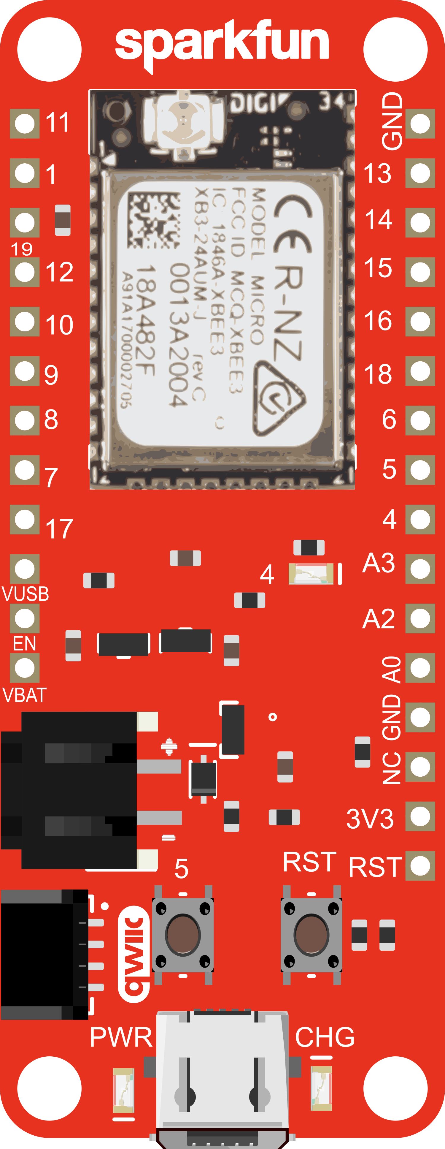
Pin Configuration and Descriptions

Pin Number Function Description
1 VCC Power supply (3.3V input)
2 DIO0 Digital I/O, configurable
3 RESET Reset pin, active low
4 DIO1 Digital I/O, configurable
5 PWM0 Pulse Width Modulation output
6 PWM1 Pulse Width Modulation output
7 SPI_CS SPI Chip Select
8 SPI_CLK SPI Clock
9 SPI_MOSI SPI Master Out Slave In
10 SPI_MISO SPI Master In Slave Out
11 I2C_SCL I2C Clock
12 I2C_SDA I2C Data
13 UART_TX UART Transmit
14 UART_RX UART Receive
15 ADC0 Analog to Digital Converter input
16 ADC1 Analog to Digital Converter input
17 ADC2 Analog to Digital Converter input
18 ADC3 Analog to Digital Converter input
19 ADC4 Analog to Digital Converter input
20 ADC5 Analog to Digital Converter input

Usage Instructions

How to Use the Component in a Circuit

  1. Powering the Device: Connect a 3.3V power supply to the VCC pin and ground to the GND pin. Alternatively, power the board via the USB-C connection or a LiPo battery.
  2. Configuring I/O Pins: Set up the desired pins as inputs or outputs using the board's firmware or through external microcontroller commands.
  3. Connecting to a Network: Utilize the XBee3 module to connect to a Zigbee network or establish a BLE connection with other devices.
  4. Programming the Board: Use the provided headers to connect the board to a computer and program it using the Arduino IDE or other compatible software.

Important Considerations and Best Practices

  • Ensure that the power supply does not exceed the recommended voltage to prevent damage.
  • Use the U.FL connector to attach an appropriate antenna for optimal wireless performance.
  • When programming the board, select the correct board and port in your development environment.
  • For low-power applications, take advantage of the board's deep sleep modes to conserve battery life.

Troubleshooting and FAQs

Common Issues Users Might Face

  • Device not powering on: Check the power supply and connections to ensure proper voltage and polarity.
  • Inability to connect to a network: Verify that the antenna is properly connected and that the network settings are correctly configured.
  • Intermittent wireless communication: Ensure there are no physical obstructions or sources of interference affecting the signal.

Solutions and Tips for Troubleshooting

  • If the device is not recognized by the computer, try using a different USB cable or port.
  • Reset the board using the RESET pin if it becomes unresponsive.
  • Update the firmware of the XBee3 module to the latest version for improved stability and performance.
  • Consult the XBee3 Micro documentation for specific configuration commands and network setup instructions.

FAQs

Q: Can the SparkFun Thing Plus - XBee3 Micro be used with Arduino IDE? A: Yes, the board is compatible with the Arduino IDE. Make sure to install the necessary board definitions and drivers.

Q: What is the range of the wireless communication? A: The range depends on the environment and antenna used but can typically reach up to 300 feet (100 meters) indoors and up to 1-2 miles (1.6-3.2 kilometers) line-of-sight outdoors with proper antenna.

Q: How do I update the firmware on the XBee3 module? A: Firmware updates can be performed using the Digi XCTU software, which is available for free from Digi International's website.

Q: Can the board be used as a standalone microcontroller? A: Yes, the SparkFun Thing Plus - XBee3 Micro has an onboard ESP32 WROOM microcontroller that can be programmed and used independently.

For further assistance, refer to the SparkFun Thing Plus - XBee3 Micro's official documentation or contact SparkFun's technical support.