How to Use Engine Stepper 5VDC up: Examples, Pinouts, and Specs
Introduction
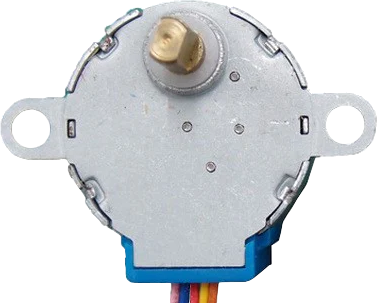
The Engine Stepper 5VDC up is a 5V DC stepper motor designed for precise control of rotation and position. Unlike standard DC motors, stepper motors move in discrete steps, making them ideal for applications requiring accurate positioning and repeatable motion. This component is widely used in robotics, 3D printers, CNC machines, and other automation systems where precision is critical.
Explore Projects Built with Engine Stepper 5VDC up


Explore Projects Built with Engine Stepper 5VDC up
Common Applications
- Robotics for precise movement and positioning
- 3D printers for controlled layer-by-layer printing
- CNC machines for accurate cutting and engraving
- Automated camera systems for smooth panning and tilting
- Industrial automation for conveyor belts and actuators
Technical Specifications
The following table outlines the key technical details of the Engine Stepper 5VDC up:
| Parameter | Value |
|---|---|
| Operating Voltage | 5V DC |
| Step Angle | 1.8° (200 steps per revolution) |
| Current per Phase | 1.2A |
| Holding Torque | 0.3 Nm |
| Number of Phases | 2 |
| Coil Resistance | 4.2Ω |
| Shaft Diameter | 5mm |
| Dimensions | 42mm x 42mm x 34mm |
| Weight | 280g |
Pin Configuration
The Engine Stepper 5VDC up typically has four wires for bipolar stepper motors or six wires for unipolar stepper motors. Below is the pin configuration for a standard 4-wire bipolar stepper motor:
| Wire Color | Function |
|---|---|
| Red | Coil A+ |
| Blue | Coil A- |
| Green | Coil B+ |
| Black | Coil B- |
For a 6-wire unipolar stepper motor, two additional wires (commonly yellow and white) are used as center taps for each coil.
Usage Instructions
How to Use the Component in a Circuit
- Power Supply: Ensure a stable 5V DC power supply capable of providing sufficient current (at least 1.2A per phase).
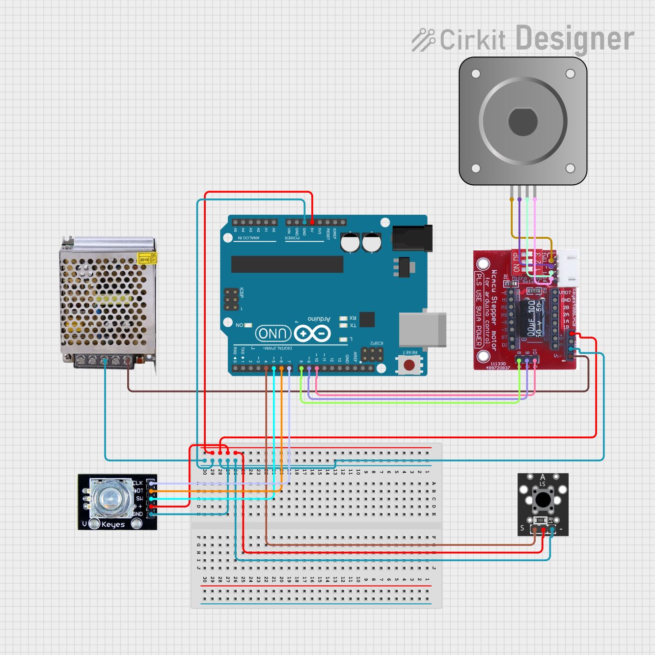
- Driver Circuit: Use a stepper motor driver (e.g., A4988 or ULN2003) to control the motor. Directly connecting the motor to a microcontroller is not recommended due to high current requirements.
- Connections:
- Connect the motor wires to the driver as per the pin configuration.
- Connect the driver's power input to the 5V power supply.
- Connect the driver's control pins (e.g., STEP and DIR) to the microcontroller.
Important Considerations
- Current Limiting: Set the current limit on the driver to match the motor's rated current (1.2A per phase) to prevent overheating.
- Microstepping: Enable microstepping on the driver for smoother motion and higher resolution.
- Heat Management: Use a heat sink or cooling fan if the motor or driver becomes excessively hot during operation.
- Back EMF Protection: Ensure the driver has built-in protection against back electromotive force (EMF) generated by the motor.
Example Code for Arduino UNO
Below is an example of how to control the Engine Stepper 5VDC up using an Arduino UNO and an A4988 driver:
// Include the Stepper library for easy motor control
#include <Stepper.h>

// Define the number of steps per revolution for the motor
#define STEPS_PER_REV 200

// Initialize the Stepper library with the motor's step count and pin connections
// Pins 8 and 9 control Coil A, Pins 10 and 11 control Coil B
Stepper stepperMotor(STEPS_PER_REV, 8, 9, 10, 11);

void setup() {
  // Set the motor speed to 60 RPM
  stepperMotor.setSpeed(60);
  // Initialize serial communication for debugging
  Serial.begin(9600);
  Serial.println("Stepper Motor Test");
}

void loop() {
  // Rotate the motor one full revolution clockwise
  Serial.println("Rotating clockwise...");
  stepperMotor.step(STEPS_PER_REV);
  delay(1000); // Wait for 1 second

  // Rotate the motor one full revolution counterclockwise
  Serial.println("Rotating counterclockwise...");
  stepperMotor.step(-STEPS_PER_REV);
  delay(1000); // Wait for 1 second
}
Notes:
- Ensure the motor driver is properly configured before running the code.
- Adjust the speed and step count as needed for your application.
Troubleshooting and FAQs
Common Issues
Motor Not Moving:
- Check all connections between the motor, driver, and microcontroller.
- Ensure the power supply is providing sufficient voltage and current.
- Verify that the driver is enabled and properly configured.
Motor Vibrates but Does Not Rotate:
- Check the wiring order of the motor coils. Incorrect wiring can cause the motor to vibrate instead of rotating.
- Ensure the stepper driver is receiving correct step and direction signals.
Overheating:
- Verify that the current limit on the driver matches the motor's rated current.
- Use a heat sink or cooling fan to dissipate heat.
Inconsistent or Jerky Motion:
- Enable microstepping on the driver for smoother operation.
- Check for loose connections or mechanical obstructions.
FAQs
Q: Can I power the motor directly from the Arduino UNO?
A: No, the Arduino UNO cannot supply the required current for the motor. Always use a dedicated motor driver and external power supply.
Q: How do I determine the correct wiring order for the motor?
A: Use a multimeter to measure the resistance between wires. Wires with the lowest resistance belong to the same coil.
Q: Can I use this motor with a 12V power supply?
A: No, the motor is designed for 5V operation. Using a higher voltage may damage the motor or driver.
Q: What is microstepping, and why is it important?
A: Microstepping divides each full step into smaller steps, providing smoother motion and higher resolution. It is especially useful for applications requiring precise positioning.