How to Use GPS: Examples, Pinouts, and Specs
Introduction
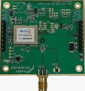
The PX1125T is a high-performance Global Positioning System (GPS) receiver module designed to determine the precise location of an object on Earth by receiving and processing signals from GPS satellites. Manufactured by GPS, this module is compact, efficient, and highly reliable, making it suitable for a wide range of applications.
Explore Projects Built with GPS


Explore Projects Built with GPS
Common Applications and Use Cases
- Navigation systems for vehicles, drones, and ships
- Geolocation tracking for IoT devices
- Surveying and mapping
- Outdoor sports and fitness devices
- Asset tracking and fleet management
- Emergency location services
Technical Specifications
The PX1125T GPS receiver is designed to deliver accurate and reliable positioning data. Below are its key technical specifications:
| Parameter | Value |
|---|---|
| Manufacturer | GPS |
| Part ID | PX1125T |
| Frequency Bands | L1 (1575.42 MHz) |
| Positioning Accuracy | 2.5 meters CEP (Circular Error Probable) |
| Sensitivity | -165 dBm tracking, -148 dBm acquisition |
| Update Rate | 1 Hz (default), configurable up to 10 Hz |
| Operating Voltage | 3.0V to 3.6V |
| Power Consumption | 25 mA (typical) |
| Communication Interface | UART, I2C |
| Operating Temperature | -40°C to +85°C |
| Dimensions | 16 mm x 12.2 mm x 2.4 mm |
Pin Configuration and Descriptions
The PX1125T module has a simple pinout for easy integration into circuits. Below is the pin configuration:
| Pin Number | Pin Name | Description |
|---|---|---|
| 1 | VCC | Power supply input (3.0V to 3.6V) |
| 2 | GND | Ground |
| 3 | TXD | UART Transmit Data (output) |
| 4 | RXD | UART Receive Data (input) |
| 5 | PPS | Pulse Per Second output for timing synchronization |
| 6 | SDA | I2C Data Line |
| 7 | SCL | I2C Clock Line |
| 8 | ANT | External antenna connection |
Usage Instructions
The PX1125T GPS module is straightforward to use in a circuit. Below are the steps and best practices for integrating and using the module:
Connecting the PX1125T to a Microcontroller
- Power Supply: Connect the VCC pin to a 3.3V power source and the GND pin to the ground.
- Communication Interface:
- For UART communication, connect the TXD pin to the RX pin of the microcontroller and the RXD pin to the TX pin of the microcontroller.
- For I2C communication, connect the SDA and SCL pins to the corresponding I2C pins on the microcontroller.
- Antenna: Attach an external GPS antenna to the ANT pin for optimal signal reception.
- PPS Signal: Use the PPS pin if precise timing synchronization is required.
Example: Using PX1125T with Arduino UNO
Below is an example of how to connect and use the PX1125T GPS module with an Arduino UNO via UART:
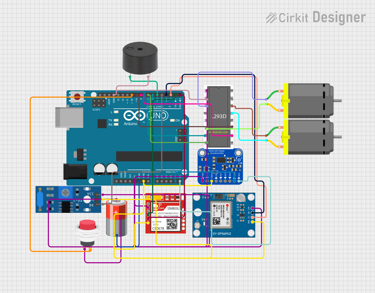
Circuit Connections
- Connect the PX1125T VCC pin to the Arduino 3.3V pin.
- Connect the PX1125T GND pin to the Arduino GND pin.
- Connect the PX1125T TXD pin to the Arduino RX (pin 0).
- Connect the PX1125T RXD pin to the Arduino TX (pin 1).
Arduino Code Example
#include <SoftwareSerial.h>

// Define RX and TX pins for SoftwareSerial
SoftwareSerial gpsSerial(10, 11); // RX = pin 10, TX = pin 11

void setup() {
  Serial.begin(9600); // Initialize Serial Monitor at 9600 baud
  gpsSerial.begin(9600); // Initialize GPS module at 9600 baud

  Serial.println("Initializing GPS module...");
}

void loop() {
  // Check if data is available from the GPS module
  while (gpsSerial.available()) {
    char c = gpsSerial.read(); // Read one character from GPS
    Serial.print(c); // Print the character to the Serial Monitor
  }
}
Best Practices
- Use a high-quality external GPS antenna for better signal reception, especially in areas with weak satellite coverage.
- Ensure the module has a clear view of the sky for optimal performance.
- Avoid placing the module near sources of electromagnetic interference (e.g., motors, power supplies).
- Use level shifters if interfacing with a 5V microcontroller to prevent damage to the module.
Troubleshooting and FAQs
Common Issues and Solutions
No GPS Fix or Location Data:
- Ensure the antenna is properly connected and has a clear view of the sky.
- Check the power supply voltage and ensure it is within the specified range (3.0V to 3.6V).
- Wait for a few minutes, as the module may take time to acquire satellite signals.
Garbage Data on Serial Monitor:
- Verify that the baud rate of the GPS module matches the baud rate in your code.
- Check the wiring between the GPS module and the microcontroller.
Module Not Responding:
- Ensure the module is powered correctly and the connections are secure.
- Test the module with a different microcontroller or UART-to-USB adapter to rule out hardware issues.
FAQs
Q: Can the PX1125T work indoors?
A: The PX1125T is designed for outdoor use and requires a clear view of the sky for optimal performance. It may work indoors near windows, but signal reception will be weaker.
Q: How many satellites does the PX1125T need for a fix?
A: The PX1125T requires signals from at least four satellites to calculate a 3D position fix (latitude, longitude, and altitude).
Q: Can I increase the update rate of the module?
A: Yes, the update rate can be configured up to 10 Hz using specific commands sent via the UART or I2C interface.
Q: Does the module support GLONASS or Galileo?
A: No, the PX1125T is designed to work with GPS satellites only.
By following this documentation, users can effectively integrate and utilize the PX1125T GPS module in their projects.