How to Use MW LRS-50-3.3V: Examples, Pinouts, and Specs

 Design with MW LRS-50-3.3V in Cirkit Designer
Introduction
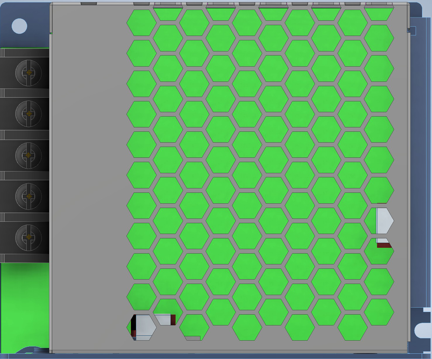
The MW LRS-50-3.3V is a compact, low-cost switching power supply designed to convert AC voltage into a stable 3.3V DC output. This highly efficient power supply is ideal for powering low-voltage electronic devices and embedded systems. Its small form factor and reliable performance make it a popular choice for industrial automation, IoT devices, LED lighting, and other applications requiring a steady 3.3V DC power source.
Explore Projects Built with MW LRS-50-3.3V

 Open Project in Cirkit Designer
 Open Project in Cirkit Designer
 Open Project in Cirkit Designer
 Open Project in Cirkit Designer
Explore Projects Built with MW LRS-50-3.3V

 Open Project in Cirkit Designer
 Open Project in Cirkit Designer
 Open Project in Cirkit Designer
 Open Project in Cirkit Designer
Common Applications
- Powering microcontrollers and single-board computers
- Industrial control systems
- LED lighting and displays
- IoT devices and sensors
- Low-voltage DC motors and actuators
Technical Specifications
The MW LRS-50-3.3V is designed to deliver consistent performance under a wide range of operating conditions. Below are its key technical specifications:
| Parameter | Value |
|---|---|
| Input Voltage Range | 85-264V AC / 120-370V DC |
| Output Voltage | 3.3V DC |
| Output Current | 10A |
| Output Power | 33W |
| Efficiency | 78% |
| Ripple and Noise | ≤80mVp-p |
| Operating Temperature | -30°C to +70°C |
| Dimensions (L x W x H) | 99 x 82 x 30 mm |
| Weight | 0.3 kg |
| Safety Standards | UL62368-1, EN62368-1, IEC62368-1 |
Pin Configuration and Descriptions
The MW LRS-50-3.3V features screw terminal connections for input and output. Below is the pin configuration:
| Pin Label | Description |
|---|---|
| L | AC Line Input (Live) |
| N | AC Neutral Input |
| FG | Frame Ground (Earth) |
| V+ | DC Output Positive (+3.3V) |
| V- | DC Output Negative (Ground) |
| V ADJ | Output Voltage Adjustment (±10% of 3.3V) |
Usage Instructions
How to Use the MW LRS-50-3.3V in a Circuit
- Input Connection: Connect the AC input terminals (L and N) to the mains power supply. Ensure the input voltage is within the specified range (85-264V AC).
- Output Connection: Connect the V+ and V- terminals to the load requiring a 3.3V DC power supply. Ensure the load does not exceed the maximum output current of 10A.
- Grounding: Connect the FG terminal to the earth ground for safety and to reduce electrical noise.
- Voltage Adjustment: If necessary, use the V ADJ potentiometer to fine-tune the output voltage within ±10% of 3.3V.
Important Considerations and Best Practices
- Heat Dissipation: Ensure adequate ventilation around the power supply to prevent overheating. Avoid enclosing the unit in a sealed box without proper airflow.
- Overload Protection: The MW LRS-50-3.3V includes overload and short-circuit protection. However, avoid operating the power supply near its maximum rated current for extended periods to ensure longevity.
- Safety Precautions: Always disconnect the power supply from the mains before making any connections or adjustments. Handle the unit with care to avoid electric shock.
- Mounting: Use the mounting holes provided on the chassis for secure installation. Avoid placing the unit near sources of excessive vibration or moisture.
Example: Powering an Arduino UNO
The MW LRS-50-3.3V can be used to power an Arduino UNO by stepping down the voltage to 3.3V. Below is an example of how to connect the power supply to the Arduino:
- Connect the V+ terminal of the power supply to the 3.3V pin on the Arduino UNO.
- Connect the V- terminal of the power supply to the GND pin on the Arduino UNO.
- Ensure the power supply is properly grounded using the FG terminal.
Here is a simple Arduino sketch to blink an LED while powered by the MW LRS-50-3.3V:
// This sketch blinks an LED connected to pin 13 of the Arduino UNO.
// Ensure the Arduino is powered by the MW LRS-50-3.3V power supply.

void setup() {
  pinMode(13, OUTPUT); // Set pin 13 as an output pin
}

void loop() {
  digitalWrite(13, HIGH); // Turn the LED on
  delay(1000);            // Wait for 1 second
  digitalWrite(13, LOW);  // Turn the LED off
  delay(1000);            // Wait for 1 second
}
Troubleshooting and FAQs
Common Issues and Solutions
No Output Voltage
- Cause: Incorrect input connections or no AC input.
- Solution: Verify that the AC input is connected to the L and N terminals and that the mains power is on.
Output Voltage Too Low or Too High
- Cause: Misadjusted V ADJ potentiometer.
- Solution: Use a small screwdriver to adjust the V ADJ potentiometer until the output voltage is 3.3V.
Overheating
- Cause: Insufficient ventilation or excessive load.
- Solution: Ensure proper airflow around the power supply and reduce the load if it exceeds 10A.
Noise or Ripple on Output
- Cause: Poor grounding or interference from nearby devices.
- Solution: Ensure the FG terminal is properly connected to earth ground and minimize interference from other devices.
FAQs
Q: Can the MW LRS-50-3.3V be used outdoors?
A: No, the power supply is not weatherproof. It should be used in a dry, indoor environment.
Q: Can I use this power supply to charge batteries?
A: The MW LRS-50-3.3V is not designed for battery charging. Use a dedicated battery charger for this purpose.
Q: What happens if the load exceeds 10A?
A: The power supply includes overload protection and will shut down temporarily to prevent damage. Reduce the load and restart the power supply.
Q: Is the output voltage adjustable?
A: Yes, the output voltage can be adjusted within ±10% of 3.3V using the V ADJ potentiometer.