How to Use Traffic Light: Examples, Pinouts, and Specs
Introduction
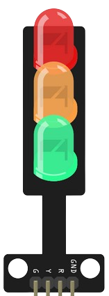
A traffic light is a signaling device that uses colored lights—red, yellow, and green—to control traffic flow at intersections. The red light signals vehicles to stop, the yellow light indicates caution and prepares drivers to stop, and the green light allows vehicles to proceed. Traffic lights are essential for maintaining order and safety in road traffic systems.
Explore Projects Built with Traffic Light
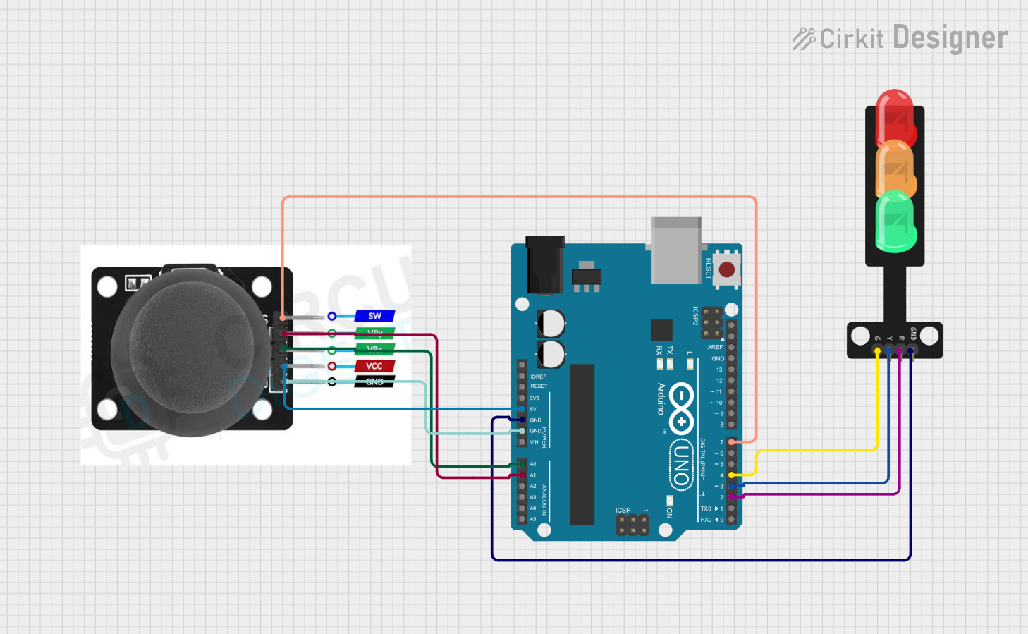
Explore Projects Built with Traffic Light
Common Applications and Use Cases
- Traffic control at road intersections
- Pedestrian crossings
- Simulated traffic systems for educational purposes
- Embedded systems and IoT projects
- Demonstrations in electronics and programming tutorials
Technical Specifications
Below are the general specifications for a standard traffic light module used in electronics projects:
| Parameter | Value |
|---|---|
| Operating Voltage | 5V DC |
| Current Consumption | ~20mA per LED |
| LED Colors | Red, Yellow, Green |
| LED Type | 5mm or 3mm standard LEDs |
| Control Pins | 3 (one for each LED) |
| Module Dimensions | Varies (commonly ~30mm x 20mm) |
Pin Configuration and Descriptions
| Pin | Name | Description |
|---|---|---|
| 1 | Red LED Pin | Controls the red LED (stop signal) |
| 2 | Yellow LED Pin | Controls the yellow LED (caution signal) |
| 3 | Green LED Pin | Controls the green LED (go signal) |
| 4 | GND | Ground connection for the module |
| 5 | VCC | Power supply input (commonly 5V DC) |
Usage Instructions
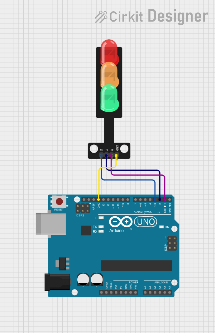
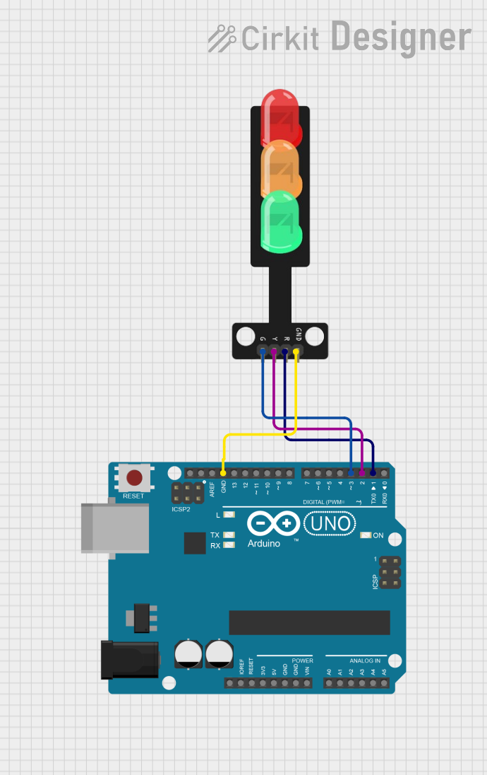
How to Use the Traffic Light in a Circuit
- Power Supply: Connect the VCC pin to a 5V DC power source and the GND pin to the ground.
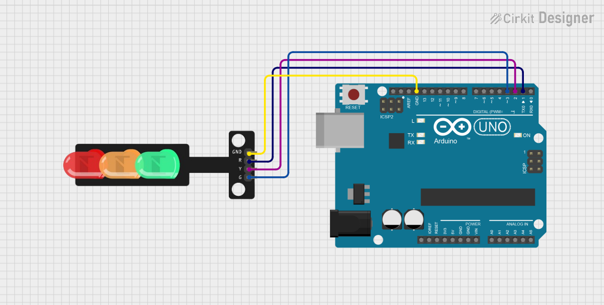
- Control Pins: Use a microcontroller (e.g., Arduino UNO) to control the red, yellow, and green LEDs by connecting the respective pins to digital output pins on the microcontroller.
- Resistors: Use appropriate current-limiting resistors (e.g., 220Ω) in series with each LED to prevent damage.
- Programming: Write a program to control the LEDs in a sequence that mimics a real traffic light.
Important Considerations and Best Practices
- Ensure the power supply voltage matches the module's operating voltage to avoid damage.
- Use resistors to limit current through the LEDs.
- Avoid leaving the LEDs on for extended periods without proper heat dissipation.
- Test the circuit on a breadboard before finalizing the design.
Example Code for Arduino UNO
Below is an example Arduino sketch to simulate a traffic light sequence:
// Pin assignments for the traffic light LEDs
const int redPin = 8;    // Red LED connected to digital pin 8
const int yellowPin = 9; // Yellow LED connected to digital pin 9
const int greenPin = 10; // Green LED connected to digital pin 10

void setup() {
  // Set the LED pins as outputs
  pinMode(redPin, OUTPUT);
  pinMode(yellowPin, OUTPUT);
  pinMode(greenPin, OUTPUT);
}

void loop() {
  // Red light ON for 5 seconds
  digitalWrite(redPin, HIGH);
  delay(5000); // Wait for 5 seconds
  digitalWrite(redPin, LOW);

  // Yellow light ON for 2 seconds
  digitalWrite(yellowPin, HIGH);
  delay(2000); // Wait for 2 seconds
  digitalWrite(yellowPin, LOW);

  // Green light ON for 5 seconds
  digitalWrite(greenPin, HIGH);
  delay(5000); // Wait for 5 seconds
  digitalWrite(greenPin, LOW);
}
Troubleshooting and FAQs
Common Issues and Solutions
LEDs Not Lighting Up:
- Check the power supply and ensure the VCC and GND connections are secure.
- Verify that the current-limiting resistors are correctly connected.
- Ensure the control pins are properly connected to the microcontroller.
Incorrect LED Sequence:
- Double-check the pin assignments in the code and ensure they match the hardware connections.
- Verify the logic in the program to ensure the correct sequence is implemented.
Dim or Flickering LEDs:
- Ensure the power supply provides sufficient current for all LEDs.
- Check for loose connections or damaged wires.
FAQs
Q: Can I use a 3.3V power supply instead of 5V?
A: Most traffic light modules are designed for 5V operation. Using 3.3V may result in dim LEDs or unreliable operation. Check the module's datasheet for compatibility.
Q: Do I need to use resistors with the LEDs?
A: Yes, resistors are necessary to limit the current through the LEDs and prevent damage.
Q: Can I control the traffic light module with a Raspberry Pi?
A: Yes, you can control the module with a Raspberry Pi by connecting the control pins to GPIO pins and using appropriate Python code.
Q: How can I add a pedestrian crossing signal?
A: You can add additional LEDs and control them using extra GPIO pins on your microcontroller. Update the code to include the pedestrian signal logic.