How to Use Raspberry pi 3b+: Examples, Pinouts, and Specs
Introduction
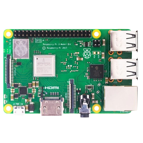
The Raspberry Pi 3B+ is a compact, affordable single-board computer designed for a wide range of applications. It features a quad-core ARM Cortex-A53 processor, multiple USB ports, HDMI output, and a 40-pin GPIO header, making it a versatile tool for DIY electronics projects, programming, and IoT applications. Its small form factor and robust performance make it ideal for hobbyists, educators, and professionals alike.
Explore Projects Built with Raspberry pi 3b+
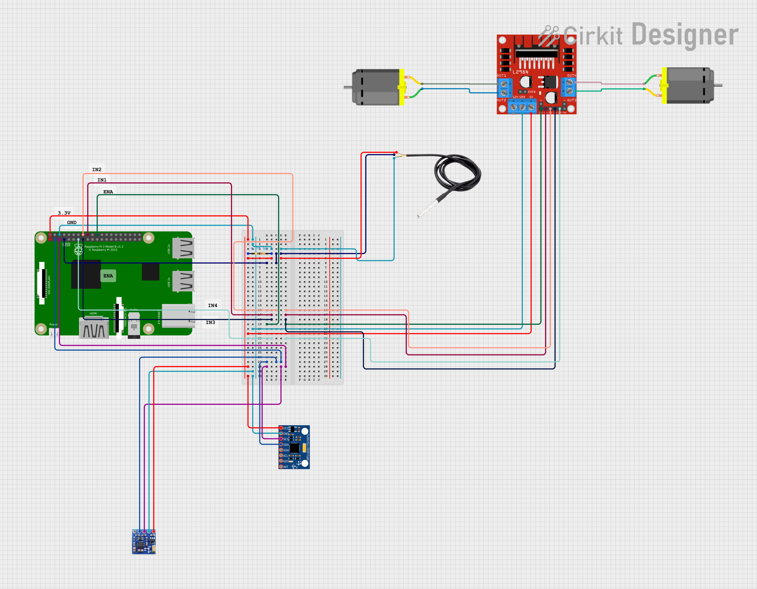
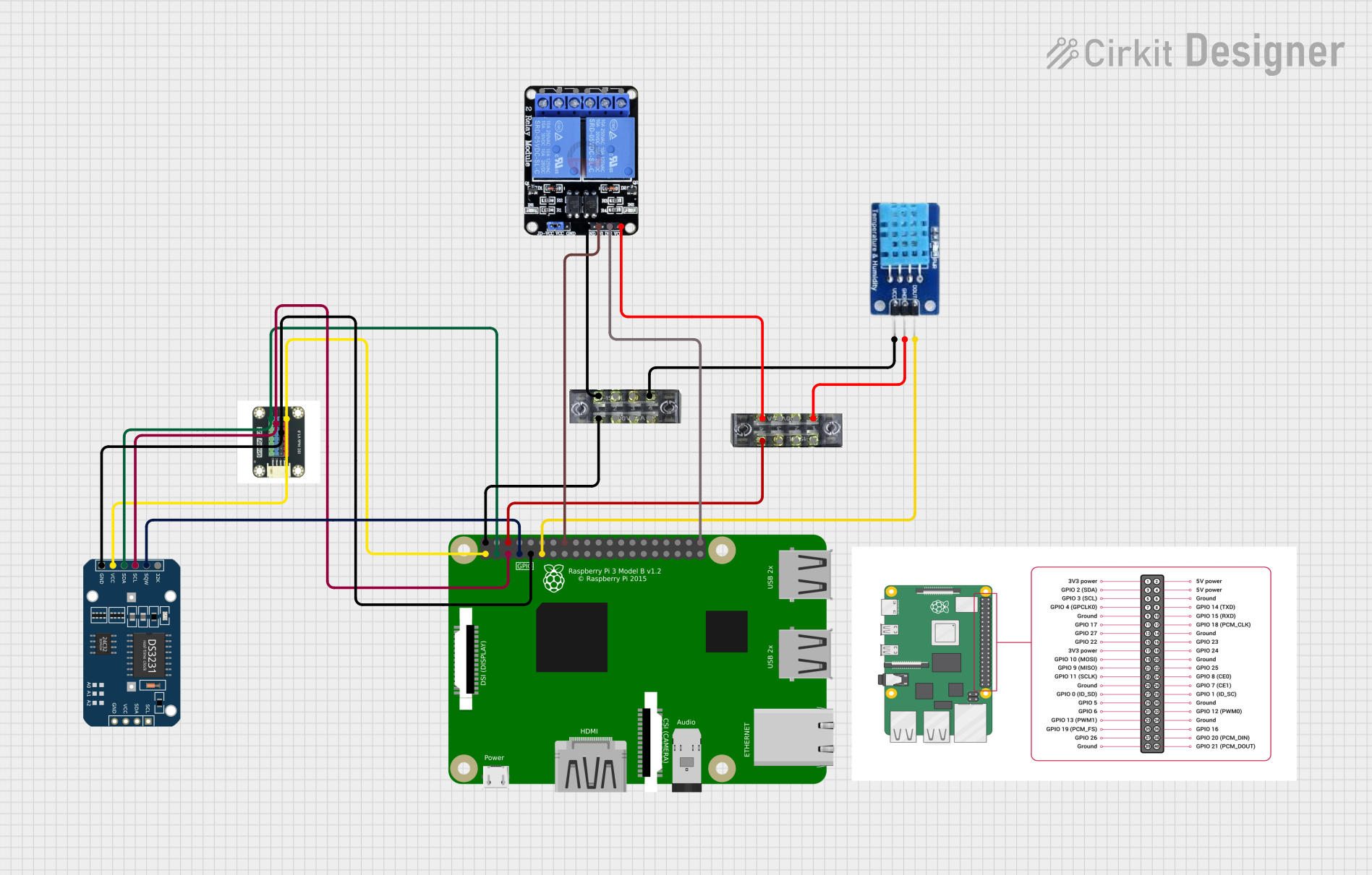
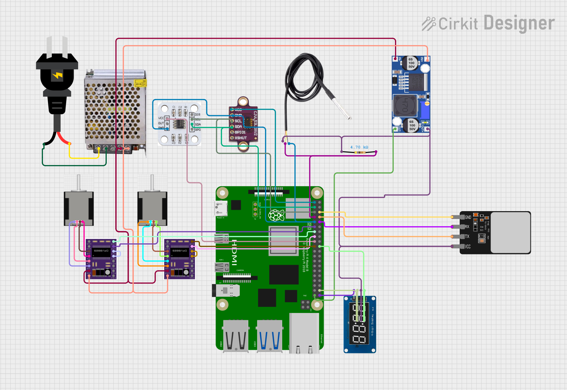
Explore Projects Built with Raspberry pi 3b+
Common Applications and Use Cases
- DIY electronics and robotics projects
- Media centers and home automation systems
- IoT (Internet of Things) devices
- Educational programming and coding platforms
- Network servers and lightweight computing tasks
Technical Specifications
The Raspberry Pi 3B+ offers a balance of performance and connectivity, making it suitable for a variety of tasks. Below are its key technical details:
Key Technical Details
| Specification | Value |
|---|---|
| Processor | Broadcom BCM2837B0, quad-core Cortex-A53 |
| Clock Speed | 1.4 GHz |
| RAM | 1 GB LPDDR2 SDRAM |
| Wireless Connectivity | 802.11ac Wi-Fi, Bluetooth 4.2 |
| Ethernet | Gigabit Ethernet (300 Mbps max throughput) |
| USB Ports | 4 x USB 2.0 |
| GPIO Header | 40-pin, 3.3V logic |
| Video Output | HDMI, Composite Video |
| Power Supply | 5V/2.5A via micro-USB |
| Dimensions | 85.6mm x 56.5mm x 17mm |
GPIO Pin Configuration
The Raspberry Pi 3B+ features a 40-pin GPIO header. Below is a summary of the pin configuration:
| Pin Number | Pin Name | Description |
|---|---|---|
| 1 | 3.3V Power | 3.3V power supply |
| 2 | 5V Power | 5V power supply |
| 3 | GPIO2 (SDA1) | I2C Data |
| 4 | 5V Power | 5V power supply |
| 5 | GPIO3 (SCL1) | I2C Clock |
| 6 | Ground | Ground |
| 7 | GPIO4 | General-purpose I/O |
| 8 | GPIO14 (TXD0) | UART Transmit |
| 9 | Ground | Ground |
| 10 | GPIO15 (RXD0) | UART Receive |
| ... | ... | ... (Refer to official GPIO pinout) |
For a complete GPIO pinout, refer to the official Raspberry Pi documentation.
Usage Instructions
How to Use the Raspberry Pi 3B+ in a Circuit
- Powering the Raspberry Pi: Use a 5V/2.5A micro-USB power supply to power the board. Ensure the power supply is stable to avoid performance issues.
- Connecting Peripherals: Attach a keyboard, mouse, and monitor via the USB and HDMI ports for initial setup. Alternatively, use SSH for headless operation.
- Booting the OS: Install an operating system (e.g., Raspberry Pi OS) on a microSD card, insert it into the microSD slot, and power on the board.
- Using GPIO Pins: Connect external components (e.g., LEDs, sensors) to the GPIO pins. Use Python libraries like
RPi.GPIOorgpiozeroto control the pins programmatically.
Important Considerations and Best Practices
- Static Protection: Handle the board with care to avoid static discharge, which can damage the components.
- Power Supply: Use a high-quality power supply to prevent undervoltage warnings and ensure stable operation.
- GPIO Voltage Levels: The GPIO pins operate at 3.3V logic. Avoid applying 5V directly to the pins to prevent damage.
- Cooling: For intensive tasks, consider using a heatsink or fan to prevent overheating.
Example: Blinking an LED with GPIO
Below is an example of how to blink an LED connected to GPIO pin 17 using Python:
Import the necessary library for GPIO control
import RPi.GPIO as GPIO import time # Import time library for delays
Set up GPIO mode and pin
GPIO.setmode(GPIO.BCM) # Use Broadcom pin numbering GPIO.setup(17, GPIO.OUT) # Set GPIO pin 17 as an output
try: while True: GPIO.output(17, GPIO.HIGH) # Turn the LED on time.sleep(1) # Wait for 1 second GPIO.output(17, GPIO.LOW) # Turn the LED off time.sleep(1) # Wait for 1 second except KeyboardInterrupt: # Clean up GPIO settings when the program is interrupted GPIO.cleanup()
Troubleshooting and FAQs
Common Issues and Solutions
The Raspberry Pi does not boot:
- Ensure the microSD card is properly inserted and contains a valid OS image.
- Check the power supply for sufficient voltage and current.
Wi-Fi or Bluetooth connectivity issues:
- Verify that the correct network credentials are entered.
- Ensure the device is within range of the Wi-Fi router.
GPIO pins not working:
- Double-check the pin connections and ensure the correct pin numbering is used in the code.
- Verify that the GPIO pins are not damaged by overvoltage.
Overheating:
- Use a heatsink or fan for cooling during intensive tasks.
- Ensure proper ventilation around the board.
FAQs
Can I power the Raspberry Pi 3B+ via GPIO pins? Yes, you can power the board using the 5V and GND pins on the GPIO header, but this bypasses the onboard voltage protection.
What is the maximum current output of the GPIO pins? Each GPIO pin can source/sink a maximum of 16mA, with a total limit of 50mA across all pins.
Can I use the Raspberry Pi 3B+ for AI/ML tasks? Yes, lightweight AI/ML tasks can be performed using frameworks like TensorFlow Lite, but performance is limited due to hardware constraints.
This concludes the documentation for the Raspberry Pi 3B+. For further details, refer to the official Raspberry Pi website and community forums.