Cirkit Designer Logo
Cirkit Designer
Your all-in-one circuit design IDE
Home / 
Component Documentation

How to Use ESP32 (30 pin): Examples, Pinouts, and Specs

Image of ESP32 (30 pin)
Cirkit Designer LogoDesign with ESP32 (30 pin) in Cirkit Designer

Introduction

The ESP32 is a powerful and versatile microcontroller designed for IoT (Internet of Things) applications and embedded systems. It features built-in Wi-Fi and Bluetooth capabilities, making it an excellent choice for projects requiring wireless communication. With its 30-pin configuration, the ESP32 provides a wide range of GPIO (General Purpose Input/Output) pins, ADC (Analog-to-Digital Converter) channels, PWM (Pulse Width Modulation) outputs, and other peripherals, enabling developers to create complex and feature-rich applications.

Explore Projects Built with ESP32 (30 pin)

Use Cirkit Designer to design, explore, and prototype these projects online. Some projects support real-time simulation. Click "Open Project" to start designing instantly!
ESP32-Based Smart Display with Camera and Audio Alert System
Image of cam_circuit_design: A project utilizing ESP32 (30 pin) in a practical application
This circuit features two ESP32 microcontrollers, one standard 30-pin version and one ESP32-CAM module, both sharing a common ground and power supply. The 30-pin ESP32 is interfaced with an I2C LCD 16x2 Screen for display purposes, using its I2C pins (D21 for SDA and D22 for SCL), and controls a buzzer connected to pin D23. Additionally, the ESP32-CAM is connected to the 30-pin ESP32 via serial communication through pins TX2 and RX2 for potential image data transfer.
Cirkit Designer LogoOpen Project in Cirkit Designer
ESP32-Based Environmental Monitoring System with Water Flow Sensing
Image of Water: A project utilizing ESP32 (30 pin) in a practical application
This circuit features an ESP32 Devkit V1 microcontroller connected to a DHT22 temperature and humidity sensor and a water flow sensor. The ESP32 reads environmental data from the DHT22 via a digital input pin (D33) and monitors water flow through the water flow sensor connected to another digital input pin (D23). The ESP32 is powered through its VIN pin, and both sensors are powered by the ESP32's 3V3 output, with common ground connections.
Cirkit Designer LogoOpen Project in Cirkit Designer
ESP32-Based OLED Display Interface
Image of d: A project utilizing ESP32 (30 pin) in a practical application
This circuit features an ESP32 microcontroller connected to an OLED 1.3" display. The ESP32's GPIO pins 21 and 22 are used for I2C communication (SDA and SCL respectively) with the OLED display. The display is powered by the 5V output from the ESP32, and both devices share a common ground.
Cirkit Designer LogoOpen Project in Cirkit Designer
ESP32-Based Environmental Monitoring System with OLED Display
Image of esproj: A project utilizing ESP32 (30 pin) in a practical application
This circuit features an ESP32 microcontroller as the central processing unit, interfacing with a DHT11 temperature and humidity sensor, an MPU-6050 accelerometer and gyroscope, an OLED display, and a separate temperature sensor. The ESP32 communicates with the MPU-6050 and the OLED display via I2C (using pins D22 and D21 for SCL and SDA, respectively), reads temperature data from the DHT11 sensor through pin D18, and interfaces with the additional temperature sensor via pin D5. All components share a common power supply connected to the ESP32's Vin pin and a common ground.
Cirkit Designer LogoOpen Project in Cirkit Designer

Explore Projects Built with ESP32 (30 pin)

Use Cirkit Designer to design, explore, and prototype these projects online. Some projects support real-time simulation. Click "Open Project" to start designing instantly!
Image of cam_circuit_design: A project utilizing ESP32 (30 pin) in a practical application
ESP32-Based Smart Display with Camera and Audio Alert System
This circuit features two ESP32 microcontrollers, one standard 30-pin version and one ESP32-CAM module, both sharing a common ground and power supply. The 30-pin ESP32 is interfaced with an I2C LCD 16x2 Screen for display purposes, using its I2C pins (D21 for SDA and D22 for SCL), and controls a buzzer connected to pin D23. Additionally, the ESP32-CAM is connected to the 30-pin ESP32 via serial communication through pins TX2 and RX2 for potential image data transfer.
Cirkit Designer LogoOpen Project in Cirkit Designer
Image of Water: A project utilizing ESP32 (30 pin) in a practical application
ESP32-Based Environmental Monitoring System with Water Flow Sensing
This circuit features an ESP32 Devkit V1 microcontroller connected to a DHT22 temperature and humidity sensor and a water flow sensor. The ESP32 reads environmental data from the DHT22 via a digital input pin (D33) and monitors water flow through the water flow sensor connected to another digital input pin (D23). The ESP32 is powered through its VIN pin, and both sensors are powered by the ESP32's 3V3 output, with common ground connections.
Cirkit Designer LogoOpen Project in Cirkit Designer
Image of d: A project utilizing ESP32 (30 pin) in a practical application
ESP32-Based OLED Display Interface
This circuit features an ESP32 microcontroller connected to an OLED 1.3" display. The ESP32's GPIO pins 21 and 22 are used for I2C communication (SDA and SCL respectively) with the OLED display. The display is powered by the 5V output from the ESP32, and both devices share a common ground.
Cirkit Designer LogoOpen Project in Cirkit Designer
Image of esproj: A project utilizing ESP32 (30 pin) in a practical application
ESP32-Based Environmental Monitoring System with OLED Display
This circuit features an ESP32 microcontroller as the central processing unit, interfacing with a DHT11 temperature and humidity sensor, an MPU-6050 accelerometer and gyroscope, an OLED display, and a separate temperature sensor. The ESP32 communicates with the MPU-6050 and the OLED display via I2C (using pins D22 and D21 for SCL and SDA, respectively), reads temperature data from the DHT11 sensor through pin D18, and interfaces with the additional temperature sensor via pin D5. All components share a common power supply connected to the ESP32's Vin pin and a common ground.
Cirkit Designer LogoOpen Project in Cirkit Designer

Common Applications and Use Cases

  • IoT devices and smart home automation
  • Wireless sensor networks
  • Wearable technology
  • Robotics and drones
  • Data logging and remote monitoring
  • Industrial automation and control systems

Technical Specifications

The ESP32 (30-pin variant) is based on the Xtensa® dual-core 32-bit LX6 microprocessor and offers a rich set of features for various applications.

Key Technical Details

Specification Value
Microcontroller Xtensa® 32-bit LX6 dual-core
Clock Speed Up to 240 MHz
Flash Memory 4 MB (varies by module)
SRAM 520 KB
Wi-Fi 802.11 b/g/n
Bluetooth v4.2 BR/EDR and BLE
Operating Voltage 3.3V
Input Voltage Range 5V (via USB) or 3.3V (via pins)
GPIO Pins 30
ADC Channels 18
PWM Outputs 16
Communication Interfaces UART, SPI, I2C, I2S, CAN, etc.
Operating Temperature Range -40°C to +125°C

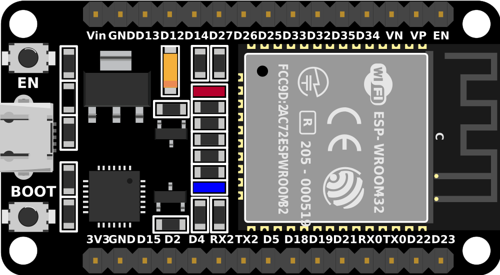
Pin Configuration and Descriptions

The ESP32 (30-pin variant) has the following pinout:

Pin Number Pin Name Description
1 EN Enable pin (active high)
2 IO1 GPIO1, UART TX, ADC, PWM
3 IO3 GPIO3, UART RX, ADC, PWM
4 IO4 GPIO4, ADC, PWM
5 IO5 GPIO5, ADC, PWM
6 GND Ground
7 IO6 GPIO6, SPI CLK
8 IO7 GPIO7, SPI MISO
9 IO8 GPIO8, SPI MOSI
10 IO9 GPIO9, ADC, PWM
... ... ... (Refer to the full datasheet for details)

Note: Some pins have multiple functions. Refer to the ESP32 datasheet for detailed pin multiplexing information.

Usage Instructions

How to Use the ESP32 in a Circuit

  1. Powering the ESP32:

    • Use a 5V power supply via the USB port or provide 3.3V directly to the 3.3V pin.
    • Ensure the power source can supply sufficient current (at least 500mA).
  2. Connecting Peripherals:

    • Use GPIO pins for digital input/output.
    • Connect sensors to ADC pins for analog input.
    • Use UART, SPI, or I2C for communication with other devices.
  3. Programming the ESP32:

    • Install the Arduino IDE and add the ESP32 board package.
    • Connect the ESP32 to your computer via a USB cable.
    • Select the correct board and port in the Arduino IDE.
  4. Uploading Code:

    • Write your code in the Arduino IDE.
    • Click the upload button to flash the code to the ESP32.

Important Considerations and Best Practices

  • Voltage Levels: The ESP32 operates at 3.3V. Avoid applying 5V to GPIO pins to prevent damage.
  • Boot Mode: Ensure the EN and BOOT buttons are used correctly during programming.
  • Power Supply: Use a stable power source to avoid unexpected resets or malfunctions.
  • Wi-Fi and Bluetooth: Avoid placing the ESP32 near metal objects or enclosures that may interfere with wireless signals.

Example Code for Arduino UNO Integration

The following example demonstrates how to connect the ESP32 to an Arduino UNO and send data via UART.

// Example: ESP32 and Arduino UNO UART Communication
// ESP32 TX -> Arduino RX
// ESP32 RX -> Arduino TX
// Ensure both devices share a common ground (GND).

void setup() {
  Serial.begin(115200); // Initialize ESP32 serial communication
  delay(1000);          // Wait for serial to stabilize
  Serial.println("ESP32 is ready to communicate!");
}

void loop() {
  if (Serial.available()) {
    // Read data from Arduino and echo it back
    String data = Serial.readString();
    Serial.println("Received: " + data);
  }
}

Note: Adjust the baud rate and connections as needed for your specific setup.

Troubleshooting and FAQs

Common Issues and Solutions

  1. ESP32 Not Detected by Computer:

    • Ensure the USB cable is functional and supports data transfer.
    • Install the correct USB-to-serial driver for your ESP32 module.
  2. Code Upload Fails:

    • Check that the correct board and port are selected in the Arduino IDE.
    • Press and hold the BOOT button while uploading the code.
  3. Wi-Fi Connection Issues:

    • Verify the SSID and password in your code.
    • Ensure the Wi-Fi network is within range and not overloaded.
  4. Random Resets or Instability:

    • Use a stable power supply with sufficient current.
    • Avoid using GPIO pins that are reserved for internal functions.

FAQs

Q: Can the ESP32 operate on 5V logic?
A: No, the ESP32 operates on 3.3V logic. Use level shifters if interfacing with 5V devices.

Q: How do I reset the ESP32?
A: Press the EN (Enable) button to reset the ESP32.

Q: Can I use the ESP32 with batteries?
A: Yes, you can power the ESP32 using a 3.7V LiPo battery with a suitable voltage regulator.

Q: How many devices can connect to the ESP32 via Bluetooth?
A: The ESP32 supports up to 7 simultaneous Bluetooth connections.

By following this documentation, you can effectively use the ESP32 (30-pin variant) in your projects and troubleshoot common issues. For more advanced features, refer to the official ESP32 datasheet and programming guide.