How to Use Adafruit Arcade Joystick: Examples, Pinouts, and Specs
Introduction
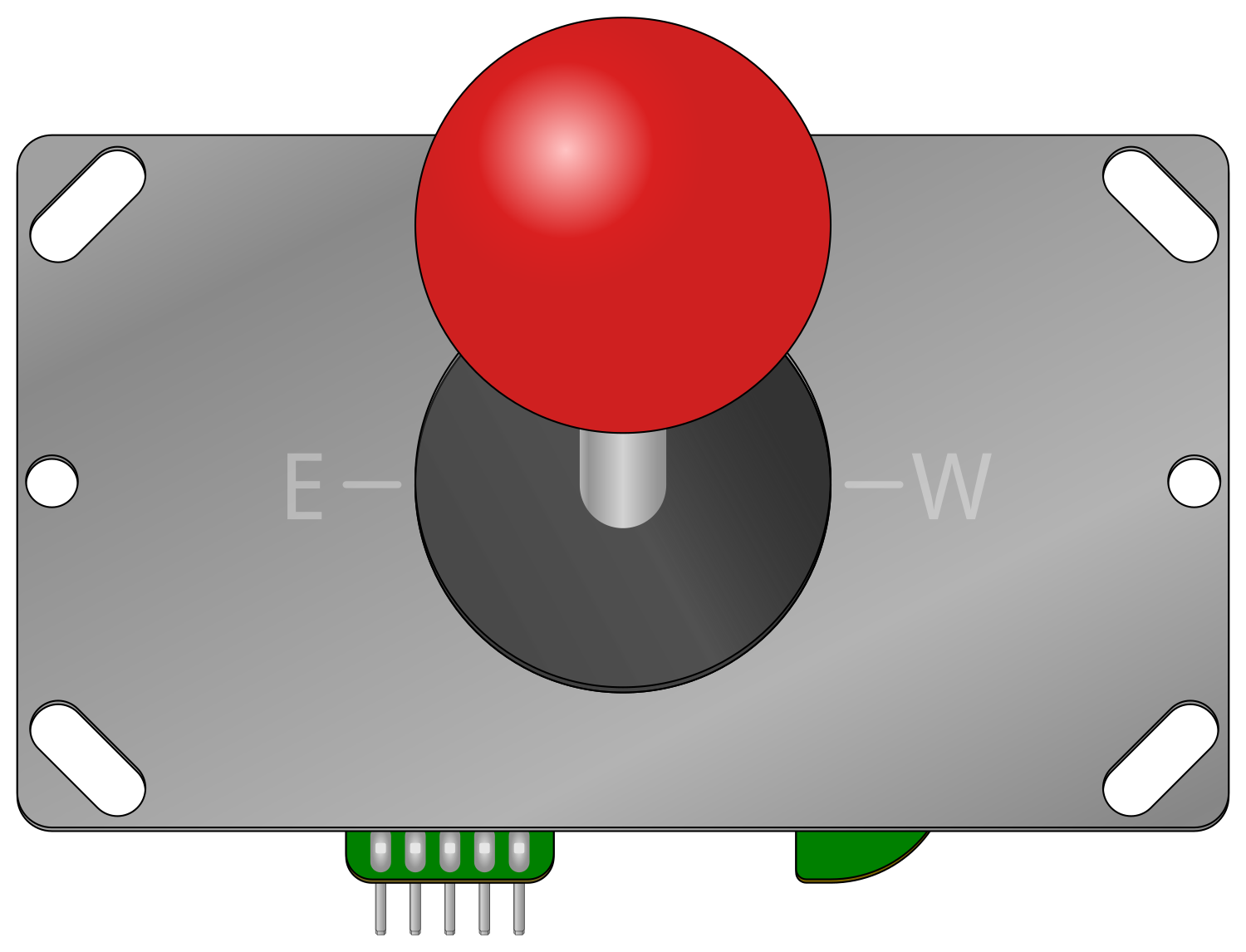
The Adafruit Arcade Joystick is a robust and responsive control device designed for arcade-style gaming on various platforms, including Raspberry Pi, Arduino, and other microcontroller-based projects. Its durable build and precise movement make it an ideal choice for DIY arcade cabinets, robotics, and interactive art installations.
Explore Projects Built with Adafruit Arcade Joystick
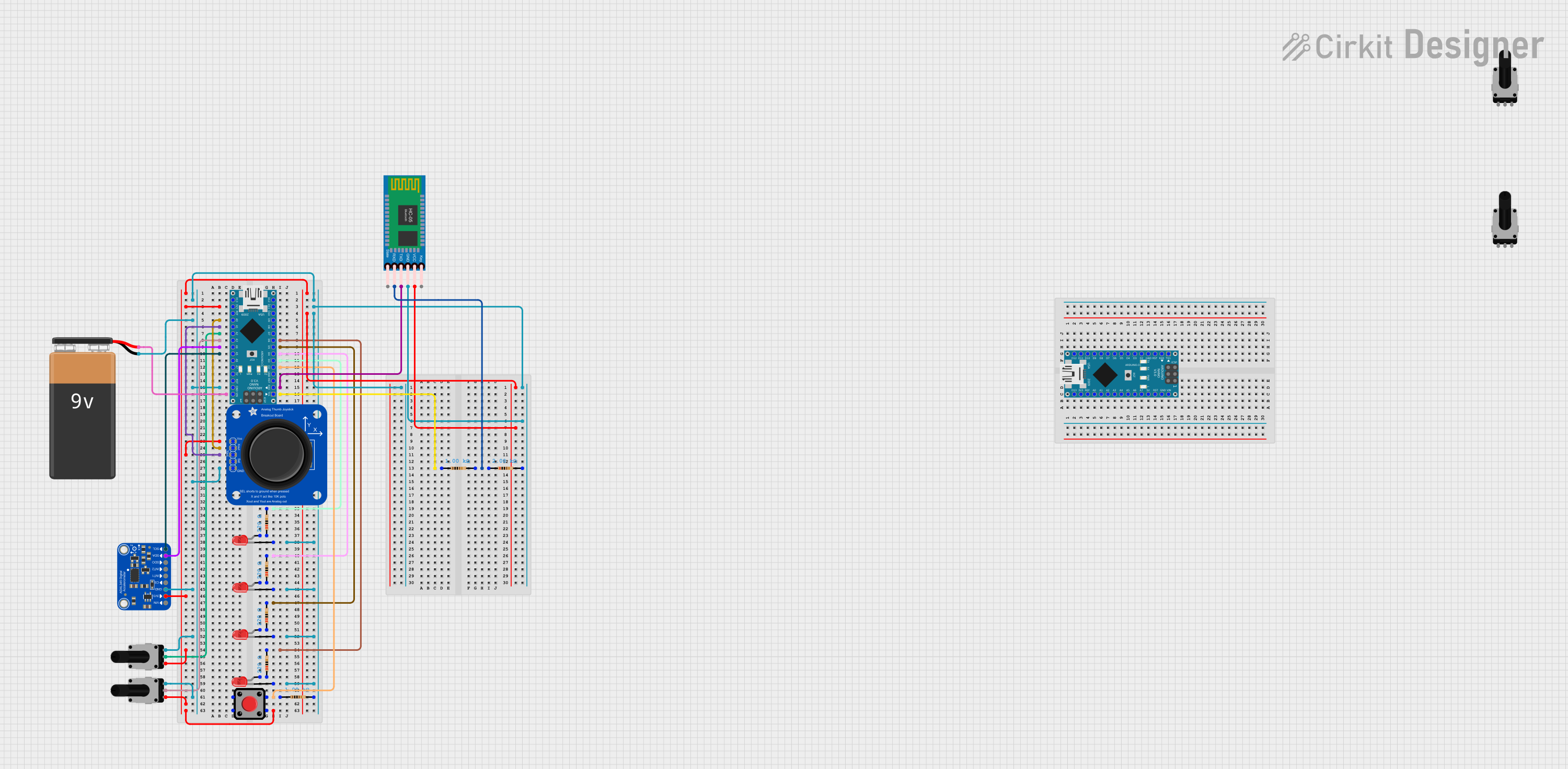
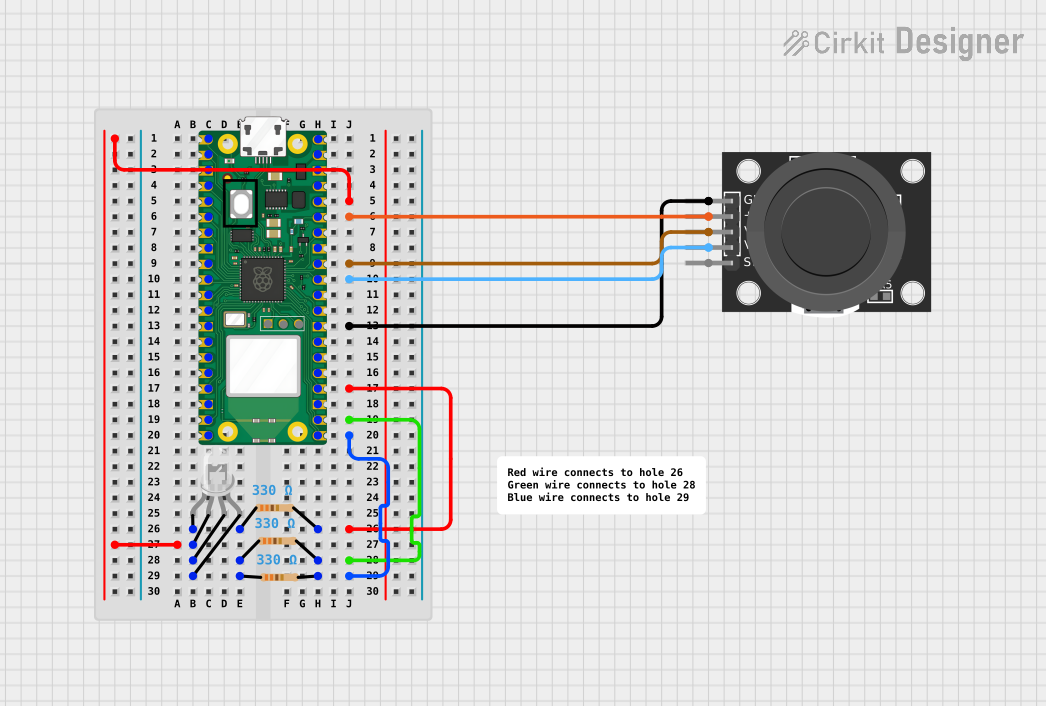
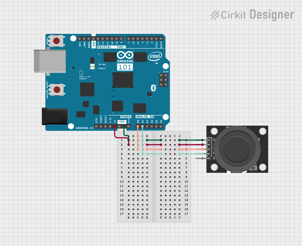
Explore Projects Built with Adafruit Arcade Joystick
Common Applications and Use Cases
- DIY arcade game cabinets
- Robotics control interfaces
- Interactive art installations
- Educational projects for learning about human-machine interfaces
Technical Specifications
Key Technical Details
- Voltage: 5V (Typical)
- Current: 10-100 mA (Depending on usage)
- Switch Type: Microswitch (4-way directional)
- Actuation Force: Approximately 75g
- Life Expectancy: 1 million cycles per switch
Pin Configuration and Descriptions
| Pin Number | Description | Notes |
|---|---|---|
| 1 | Ground (GND) | Connect to system ground |
| 2 | Up Signal | Active LOW when joystick is up |
| 3 | Down Signal | Active LOW when joystick is down |
| 4 | Left Signal | Active LOW when joystick is left |
| 5 | Right Signal | Active LOW when joystick is right |
| 6 | +5V Power Supply (VCC) | Connect to 5V power source |
Usage Instructions
How to Use the Component in a Circuit
- Power Connections: Connect the VCC pin to a 5V power supply and the GND pin to the ground of your system.
- Signal Connections: Connect the Up, Down, Left, and Right signal pins to the digital input pins on your microcontroller.
- Pull-up Resistors: It is recommended to use internal or external pull-up resistors on the signal lines to ensure a high signal when the joystick is in the neutral position.
Important Considerations and Best Practices
- Debounce: Implement software debouncing to prevent false readings due to the mechanical nature of the switches.
- Mounting: Secure the joystick firmly to your project enclosure to ensure accurate and consistent control.
- Cable Management: Keep wires organized to prevent interference with the joystick's movement.
Example Code for Arduino UNO
// Define the digital pins connected to the joystick
const int pinUp = 2;
const int pinDown = 3;
const int pinLeft = 4;
const int pinRight = 5;

void setup() {
  // Initialize the joystick pins as inputs with internal pull-up resistors
  pinMode(pinUp, INPUT_PULLUP);
  pinMode(pinDown, INPUT_PULLUP);
  pinMode(pinLeft, INPUT_PULLUP);
  pinMode(pinRight, INPUT_PULLUP);
}

void loop() {
  // Read the state of the joystick and print the direction to the Serial Monitor
  if (digitalRead(pinUp) == LOW) {
    Serial.println("Joystick moved up");
  }
  if (digitalRead(pinDown) == LOW) {
    Serial.println("Joystick moved down");
  }
  if (digitalRead(pinLeft) == LOW) {
    Serial.println("Joystick moved left");
  }
  if (digitalRead(pinRight) == LOW) {
    Serial.println("Joystick moved right");
  }

  // Add a small delay to prevent overwhelming the Serial Monitor
  delay(100);
}
Troubleshooting and FAQs
Common Issues Users Might Face
- Joystick not responding: Ensure all connections are secure and the power supply is at 5V.
- Erratic movements: Implement debouncing in your code to filter out noise from the switch contacts.
- Sticking or rough movement: Check for obstructions or misalignment in the joystick's physical assembly.
Solutions and Tips for Troubleshooting
- Check Connections: Verify that all wires are connected properly and there are no loose connections.
- Test Switches: Use a multimeter to test each microswitch in the joystick for proper operation.
- Software Debounce: Implement a debounce algorithm in your code to account for the mechanical switch bounce.
FAQs
Q: Can I use the Adafruit Arcade Joystick with a 3.3V system? A: Yes, but ensure that the logic levels are compatible with your microcontroller.
Q: How can I customize the joystick's feel or tension? A: The joystick's tension can typically be adjusted by tightening or loosening the screws on the spring mechanism. However, this may vary depending on the specific model.
Q: What is the best way to clean the joystick? A: Use a soft, dry cloth to remove dust. For sticky residues, use a cloth dampened with isopropyl alcohol, but avoid letting any liquid seep into the switches.
Remember to always turn off and disconnect power before performing any maintenance on electronic components.