How to Use 4 channel usb 5v: Examples, Pinouts, and Specs
Introduction
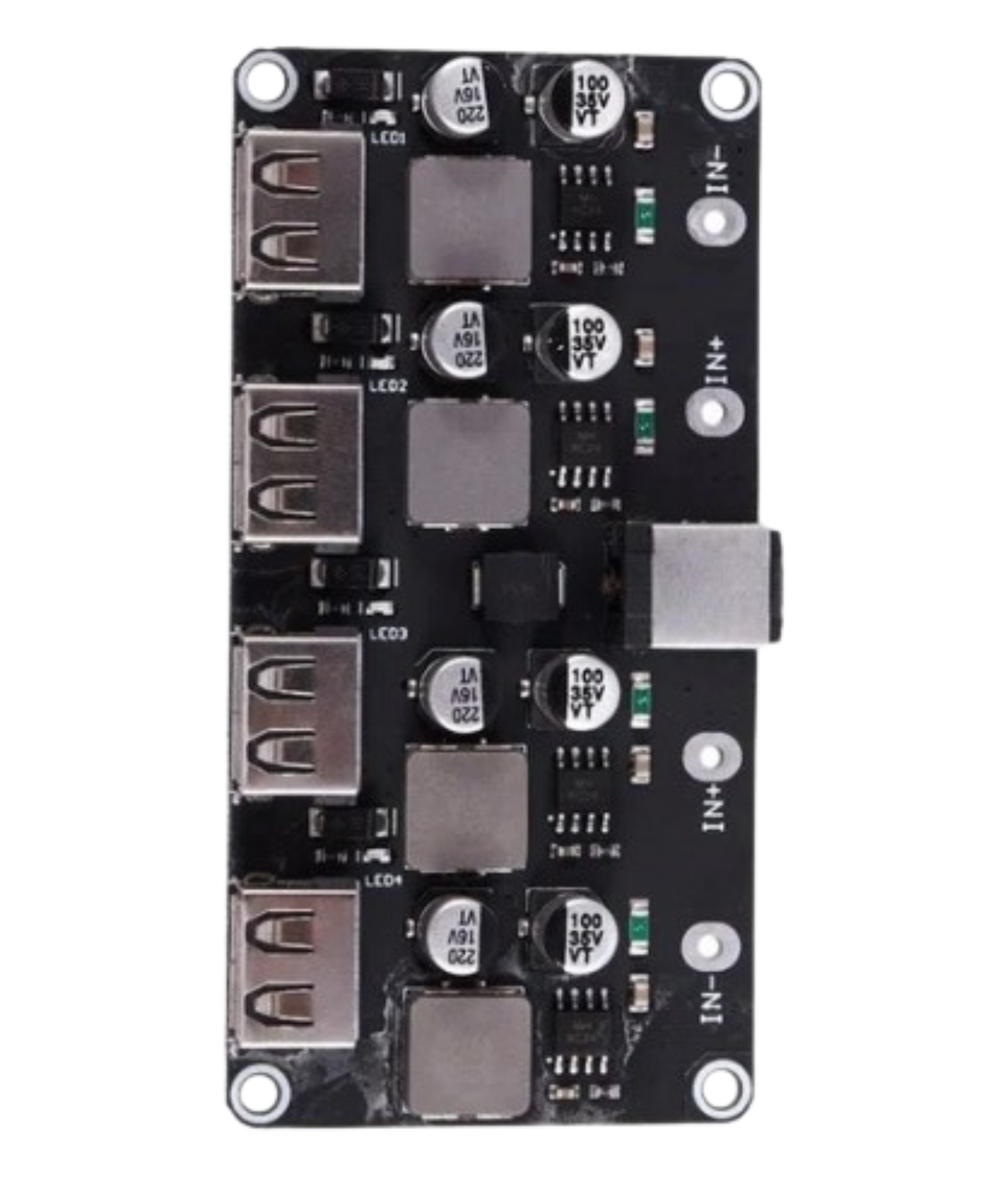
The 4-Channel USB 5V Power Supply by Drok (Manufacturer Part ID: 4-Channel USB stepdown DC to DC) is a versatile power supply module designed to provide stable 5V power to multiple devices simultaneously. This component is ideal for powering various electronic projects, including microcontrollers, sensors, and other peripherals, making it a valuable addition to any electronics toolkit.
Explore Projects Built with 4 channel usb 5v


Explore Projects Built with 4 channel usb 5v
Common Applications and Use Cases
- Microcontroller Projects: Powering Arduino, Raspberry Pi, and other microcontroller boards.
- Sensor Networks: Providing power to multiple sensors in a distributed network.
- Portable Electronics: Charging and powering USB devices such as smartphones, tablets, and portable gadgets.
- Prototyping and Development: Supplying power to breadboards and development boards during prototyping.
Technical Specifications
Key Technical Details
| Parameter | Value |
|---|---|
| Input Voltage | 6V - 32V DC |
| Output Voltage | 5V DC |
| Output Current | Up to 3A per channel |
| Total Power Output | 60W (15W per channel) |
| Efficiency | Up to 95% |
| Operating Temperature | -40°C to 85°C |
| Dimensions | 60mm x 50mm x 20mm |
Pin Configuration and Descriptions
| Pin No. | Pin Name | Description |
|---|---|---|
| 1 | VIN | Input Voltage (6V - 32V DC) |
| 2 | GND | Ground |
| 3 | VOUT1 | 5V Output Channel 1 |
| 4 | VOUT2 | 5V Output Channel 2 |
| 5 | VOUT3 | 5V Output Channel 3 |
| 6 | VOUT4 | 5V Output Channel 4 |
Usage Instructions
How to Use the Component in a Circuit
Connect the Input Voltage:
- Connect the positive terminal of your power source (6V - 32V DC) to the
VINpin. - Connect the negative terminal of your power source to the
GNDpin.
- Connect the positive terminal of your power source (6V - 32V DC) to the
Connect the Output Channels:
- Connect your devices to the
VOUT1,VOUT2,VOUT3, andVOUT4pins as needed. - Ensure that the total current drawn from each channel does not exceed 3A.
- Connect your devices to the
Power On:
- Once all connections are secure, power on your input voltage source.
- The module will step down the input voltage to a stable 5V output across all channels.
Important Considerations and Best Practices
- Heat Dissipation: Ensure adequate ventilation or cooling, especially when drawing high currents, to prevent overheating.
- Input Voltage Range: Do not exceed the specified input voltage range (6V - 32V DC) to avoid damaging the module.
- Current Limiting: Be mindful of the current limits per channel (3A) and the total power output (60W) to ensure safe operation.
- Polarity: Double-check the polarity of your connections to avoid reverse polarity damage.
Troubleshooting and FAQs
Common Issues and Solutions
No Output Voltage:
- Check Input Voltage: Ensure the input voltage is within the specified range (6V - 32V DC).
- Verify Connections: Double-check all connections, especially the
VINandGNDpins. - Inspect for Damage: Look for any visible damage or burnt components on the module.
Overheating:
- Reduce Load: Ensure the current drawn from each channel does not exceed 3A.
- Improve Cooling: Add a heatsink or improve ventilation around the module.
Inconsistent Output Voltage:
- Stable Input: Ensure the input voltage is stable and within the specified range.
- Check Load: Verify that the connected devices are not drawing more current than the module can supply.
FAQs
Q1: Can I use this module to charge my smartphone?
- A1: Yes, you can use this module to charge USB devices, including smartphones, as long as the total current drawn does not exceed the module's limits.
Q2: Can I connect more than one device to a single output channel?
- A2: Yes, you can connect multiple devices to a single output channel, but ensure the total current drawn from that channel does not exceed 3A.
Q3: Is this module compatible with Arduino and Raspberry Pi?
- A3: Yes, this module can provide stable 5V power to Arduino, Raspberry Pi, and other microcontroller boards.
Example Code for Arduino UNO
Here is an example of how to use the 4-Channel USB 5V Power Supply to power an Arduino UNO and control an LED:
// Example code to control an LED using Arduino UNO powered by the 4-Channel USB 5V Power Supply

const int ledPin = 13; // Pin connected to the LED

void setup() {
  pinMode(ledPin, OUTPUT); // Set the LED pin as an output
}

void loop() {
  digitalWrite(ledPin, HIGH); // Turn the LED on
  delay(1000); // Wait for 1 second
  digitalWrite(ledPin, LOW); // Turn the LED off
  delay(1000); // Wait for 1 second
}
In this example, the Arduino UNO is powered by one of the 5V output channels from the 4-Channel USB 5V Power Supply. The code simply toggles an LED on and off every second.
This documentation provides a comprehensive overview of the 4-Channel USB 5V Power Supply by Drok, including its technical specifications, usage instructions, and troubleshooting tips. Whether you are a beginner or an experienced user, this guide will help you effectively utilize this versatile power supply module in your electronic projects.