How to Use Breakoutboard: Examples, Pinouts, and Specs
Introduction
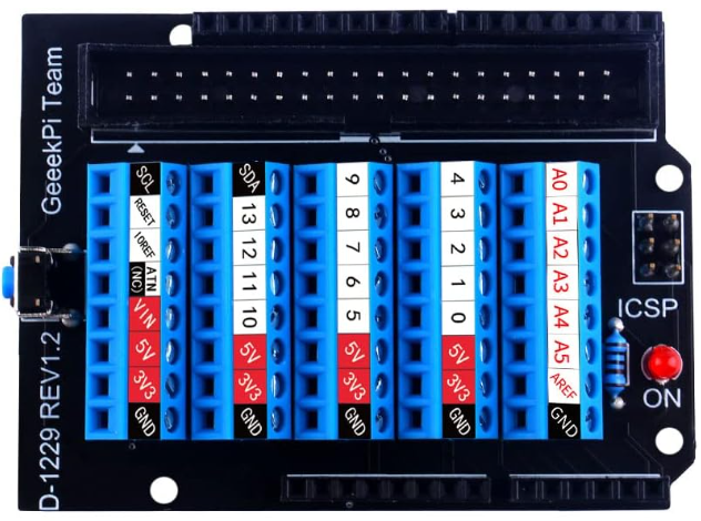
A breakout board, manufactured by GeeekPi, is a small printed circuit board (PCB) designed to simplify prototyping and testing by providing easy access to the pins of a component, such as an integrated circuit (IC). It "breaks out" the pins of a component into a more manageable layout, often with headers or screw terminals, making it easier to connect to other components or breadboards.
Explore Projects Built with Breakoutboard
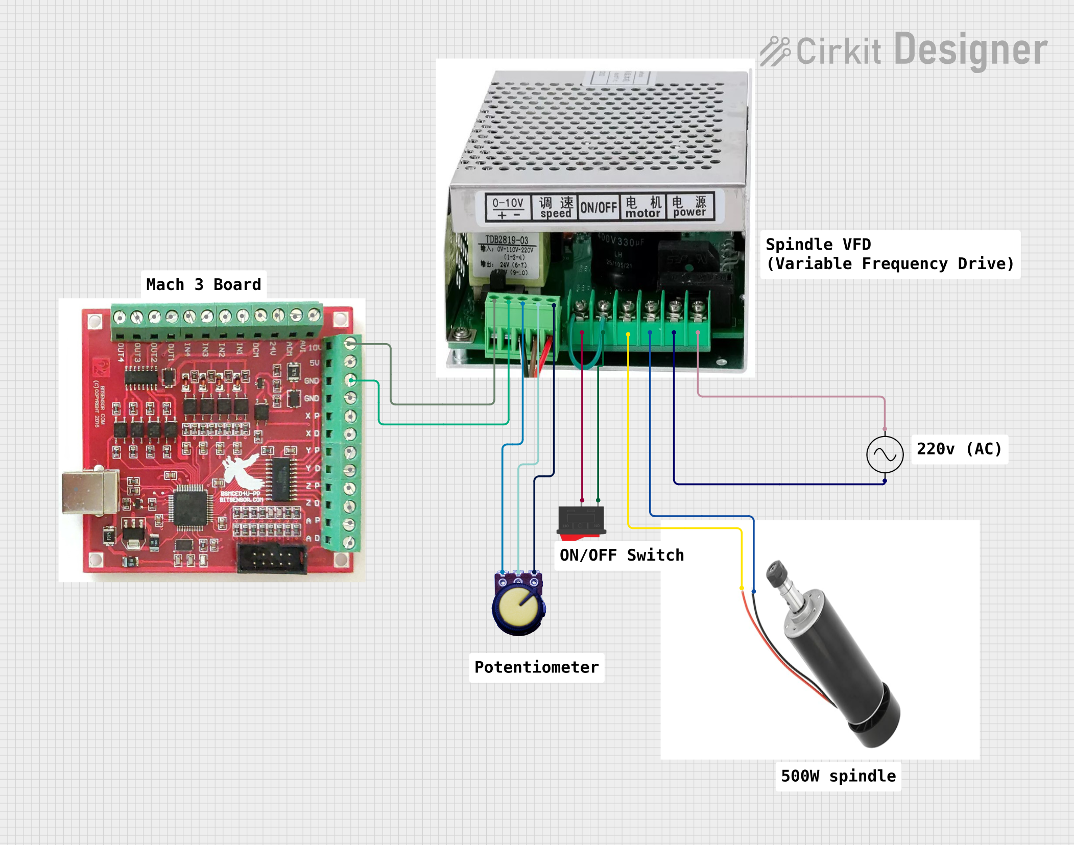
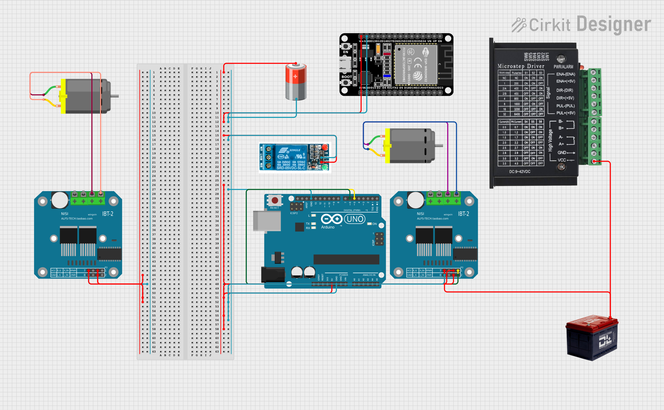
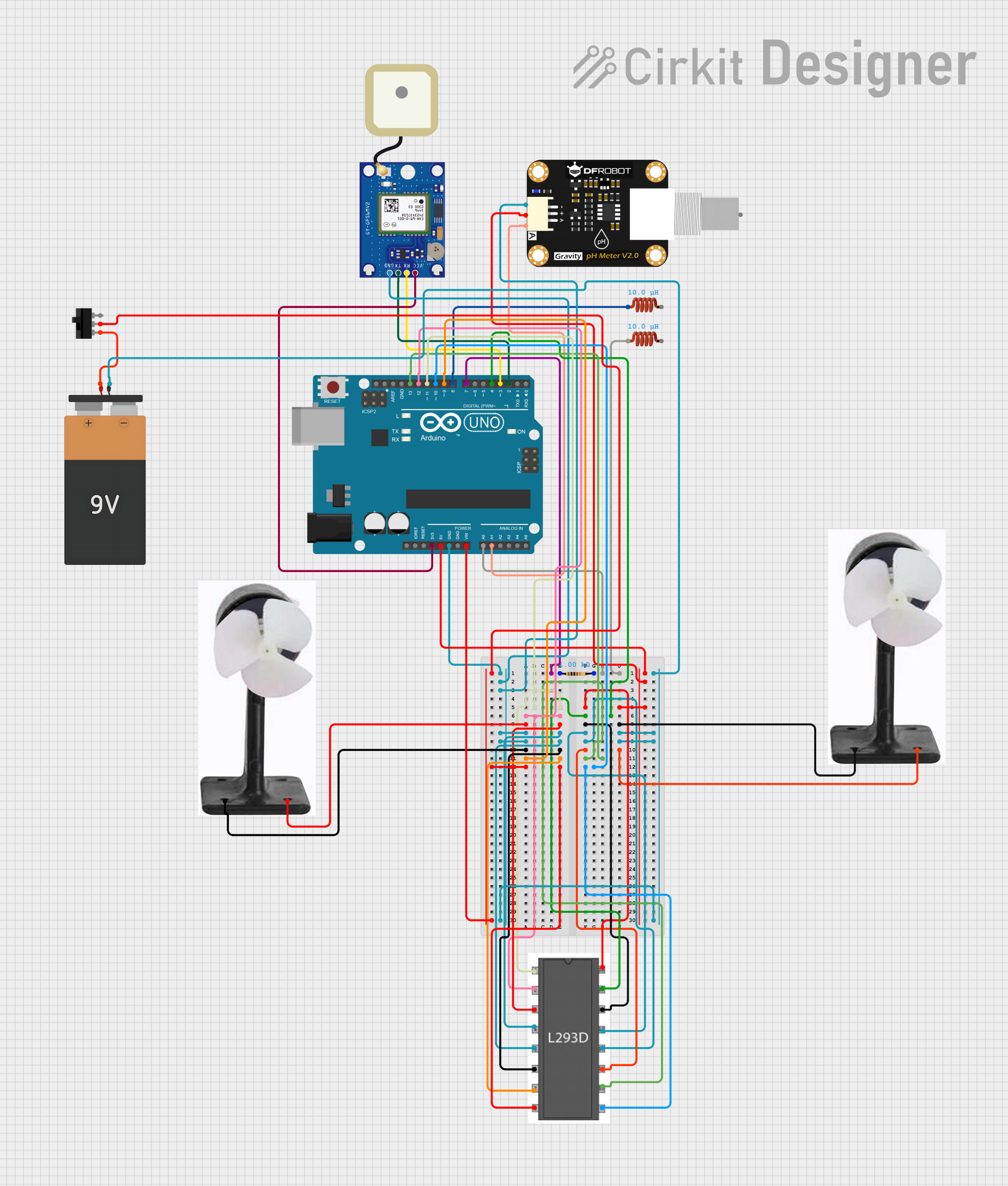
Explore Projects Built with Breakoutboard
Common Applications and Use Cases
- Prototyping circuits with integrated circuits (ICs) or sensors.
- Testing and debugging electronic components.
- Interfacing small surface-mount devices (SMDs) with breadboards.
- Educational purposes for learning about electronics and circuit design.
Technical Specifications
The GeeekPi breakout board is designed to be versatile and compatible with a wide range of components. Below are the key technical details:
General Specifications
| Parameter | Value |
|---|---|
| Manufacturer | GeeekPi |
| PCB Material | FR4 (Flame Retardant) |
| Supported Components | ICs, sensors, SMDs, etc. |
| Pin Pitch | 2.54 mm (standard breadboard) |
| Operating Voltage Range | 3.3V to 5V |
| Dimensions | Varies by model |
Pin Configuration and Descriptions
The breakout board typically includes the following pin configurations, depending on the specific model:
| Pin Name | Description |
|---|---|
| VCC | Power input pin (3.3V or 5V, depending on the component used). |
| GND | Ground connection. |
| Signal Pins | Pins connected to the component's I/O for data or control signals. |
| NC | Not connected (may be present for alignment or unused pins). |
Note: The exact pin configuration may vary depending on the specific breakout board model and the component it is designed for. Always refer to the datasheet of the component being used.
Usage Instructions
How to Use the Breakout Board in a Circuit
- Identify the Component and Pinout: Determine the pinout of the component you want to use with the breakout board. Refer to the component's datasheet for details.
- Solder the Component: Carefully solder the component onto the breakout board. Ensure proper alignment of pins.
- Connect to a Breadboard or Circuit:
- Insert the breakout board's header pins into a breadboard or connect wires to the pins.
- Use the labeled pins (e.g., VCC, GND, Signal) to connect the breakout board to your circuit.
- Power the Circuit: Provide the appropriate voltage (3.3V or 5V) to the VCC pin and connect the GND pin to the ground of your circuit.
- Test the Circuit: Verify the connections and test the functionality of the component.
Important Considerations and Best Practices
- Voltage Compatibility: Ensure the breakout board and the connected component are compatible with the operating voltage of your circuit.
- Soldering: Use a fine-tipped soldering iron and appropriate solder to avoid damaging the component or PCB.
- Pin Alignment: Double-check the alignment of the component's pins with the breakout board before soldering.
- Avoid Overheating: Do not overheat the PCB or component during soldering to prevent damage.
Example: Using a Breakout Board with an Arduino UNO
Below is an example of connecting a breakout board with a temperature sensor to an Arduino UNO:
Circuit Connections
- Connect the breakout board's VCC pin to the Arduino's 5V pin.
- Connect the GND pin to the Arduino's GND pin.
- Connect the Signal pin (e.g., data output from the sensor) to an Arduino digital or analog input pin (e.g., A0).
Arduino Code Example
// Example code for reading data from a sensor on a breakout board
// connected to an Arduino UNO. The sensor's signal pin is connected
// to analog pin A0.

const int sensorPin = A0; // Define the analog pin connected to the sensor
int sensorValue = 0;      // Variable to store the sensor reading

void setup() {
  Serial.begin(9600); // Initialize serial communication at 9600 baud
}

void loop() {
  sensorValue = analogRead(sensorPin); // Read the sensor value
  Serial.print("Sensor Value: ");      // Print the sensor value to the serial monitor
  Serial.println(sensorValue);
  delay(1000); // Wait for 1 second before the next reading
}
Troubleshooting and FAQs
Common Issues and Solutions
No Output or Incorrect Readings:
- Cause: Incorrect wiring or loose connections.
- Solution: Double-check all connections and ensure the pins are properly aligned.
Component Overheating:
- Cause: Incorrect voltage supplied to the breakout board.
- Solution: Verify the operating voltage of the component and ensure it matches the power supply.
Soldering Issues:
- Cause: Poor solder joints or solder bridges.
- Solution: Inspect the solder joints and re-solder if necessary. Use a solder wick to remove excess solder.
Breadboard Compatibility:
- Cause: Pins not fitting properly into the breadboard.
- Solution: Ensure the breakout board uses standard 2.54 mm pin spacing.
FAQs
Q: Can I use the breakout board with surface-mount devices (SMDs)?
A: Yes, many breakout boards are designed to accommodate SMDs. Ensure the breakout board matches the pin layout of your SMD component.
Q: Is the breakout board compatible with 3.3V and 5V systems?
A: Yes, most GeeekPi breakout boards are compatible with both 3.3V and 5V systems. Verify the voltage requirements of your specific component.
Q: Do I need to solder the component to the breakout board?
A: Yes, soldering is typically required to securely attach the component to the breakout board.
Q: Can I reuse the breakout board with a different component?
A: Yes, but you may need to desolder the current component and clean the PCB before reusing it.
By following this documentation, you can effectively use the GeeekPi breakout board for prototyping and testing your electronic projects.