How to Use OPT101 Light Sensor: Examples, Pinouts, and Specs
Introduction
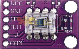
The OPT101 is a monolithic photodiode and single-supply transimpedance amplifier integrated into a single chip, designed for light measurement applications. This component is highly versatile and can be used in various applications such as:
- Ambient light sensing
- Optical power measurement
- Light-based proximity sensing
- Medical instrumentation
- Industrial automation
The OPT101 simplifies the design of light measurement systems by integrating the photodiode and amplifier into a single package, reducing the need for external components and improving overall system reliability.
Explore Projects Built with OPT101 Light Sensor
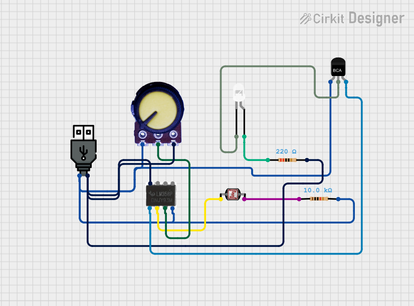
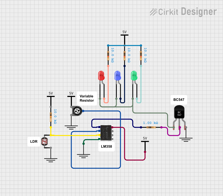
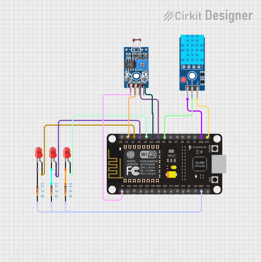

Explore Projects Built with OPT101 Light Sensor
Technical Specifications
Key Technical Details
| Parameter | Value |
|---|---|
| Supply Voltage (Vcc) | 2.7V to 36V |
| Supply Current | 120 µA (typical) |
| Output Voltage Range | 0V to (Vcc - 1.8V) |
| Photodiode Sensitivity | 0.45 A/W (at 650 nm) |
| Bandwidth | 14 kHz |
| Operating Temperature | -40°C to +85°C |
| Package | 8-pin DIP or SOIC |
Pin Configuration and Descriptions
| Pin Number | Pin Name | Description |
|---|---|---|
| 1 | Vcc | Positive power supply |
| 2 | NC | No connection |
| 3 | NC | No connection |
| 4 | Out | Output voltage |
| 5 | NC | No connection |
| 6 | NC | No connection |
| 7 | Common | Ground |
| 8 | NC | No connection |
Usage Instructions
How to Use the Component in a Circuit
To use the OPT101 light sensor in a circuit, follow these steps:
- Power Supply: Connect the Vcc pin (Pin 1) to a positive power supply (2.7V to 36V). Connect the Common pin (Pin 7) to the ground of the power supply.
- Output: Connect the Out pin (Pin 4) to the input of an analog-to-digital converter (ADC) or any other measurement device to read the output voltage corresponding to the light intensity.
Important Considerations and Best Practices
- Power Supply Decoupling: Place a 0.1 µF capacitor close to the Vcc pin to filter out any noise from the power supply.
- Output Load: Ensure that the load connected to the output pin does not exceed the recommended output current to avoid distortion.
- Ambient Light: Be aware of the ambient light conditions in your application, as they can affect the sensor's readings.
Example Circuit with Arduino UNO
Here is an example of how to connect the OPT101 light sensor to an Arduino UNO:
OPT101 Pin 1 (Vcc)  -> Arduino 5V
OPT101 Pin 4 (Out)  -> Arduino A0
OPT101 Pin 7 (Common) -> Arduino GND
Example Code for Arduino UNO
// Define the analog pin connected to the OPT101 output
const int sensorPin = A0;

void setup() {
  // Initialize serial communication at 9600 baud rate
  Serial.begin(9600);
}

void loop() {
  // Read the analog value from the sensor
  int sensorValue = analogRead(sensorPin);

  // Convert the analog value to voltage (assuming 5V reference)
  float voltage = sensorValue * (5.0 / 1023.0);

  // Print the voltage to the serial monitor
  Serial.print("Light Sensor Voltage: ");
  Serial.println(voltage);

  // Wait for 500 milliseconds before the next reading
  delay(500);
}
Troubleshooting and FAQs
Common Issues Users Might Face
- No Output Voltage: Ensure that the power supply is connected correctly and that the sensor is receiving the correct voltage.
- Fluctuating Readings: Check for noise in the power supply and add a decoupling capacitor if necessary. Ensure that the sensor is not exposed to rapidly changing light conditions.
- Incorrect Readings: Verify the connections and ensure that the output is connected to a high-impedance input to avoid loading effects.
Solutions and Tips for Troubleshooting
- Check Connections: Double-check all connections to ensure they are secure and correct.
- Power Supply: Ensure that the power supply voltage is within the specified range and is stable.
- Shielding: If the sensor is used in a noisy environment, consider shielding the sensor and its connections to reduce interference.
- Calibration: Calibrate the sensor in your specific application environment to account for any variations in ambient light or other factors.
By following this documentation, users should be able to effectively integrate and utilize the OPT101 light sensor in their projects, whether they are beginners or experienced users.