How to Use Adafruit SI1145 Digital UV Index + IR + Visible Light Sensor: Examples, Pinouts, and Specs
Introduction
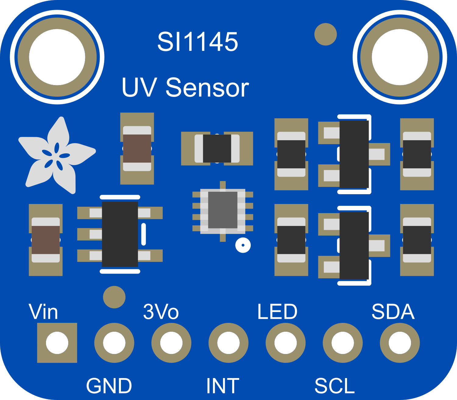
The Adafruit SI1145 is a multifunctional sensor capable of detecting ultraviolet (UV) light, infrared (IR) light, and visible light. It is designed to measure the UV Index, which is an international standard measurement of the strength of sunburn-producing ultraviolet radiation at a particular place and time. Additionally, it can measure IR levels and ambient light levels, making it a versatile choice for environmental monitoring, weather stations, or projects requiring light sensing capabilities.
Explore Projects Built with Adafruit SI1145 Digital UV Index + IR + Visible Light Sensor
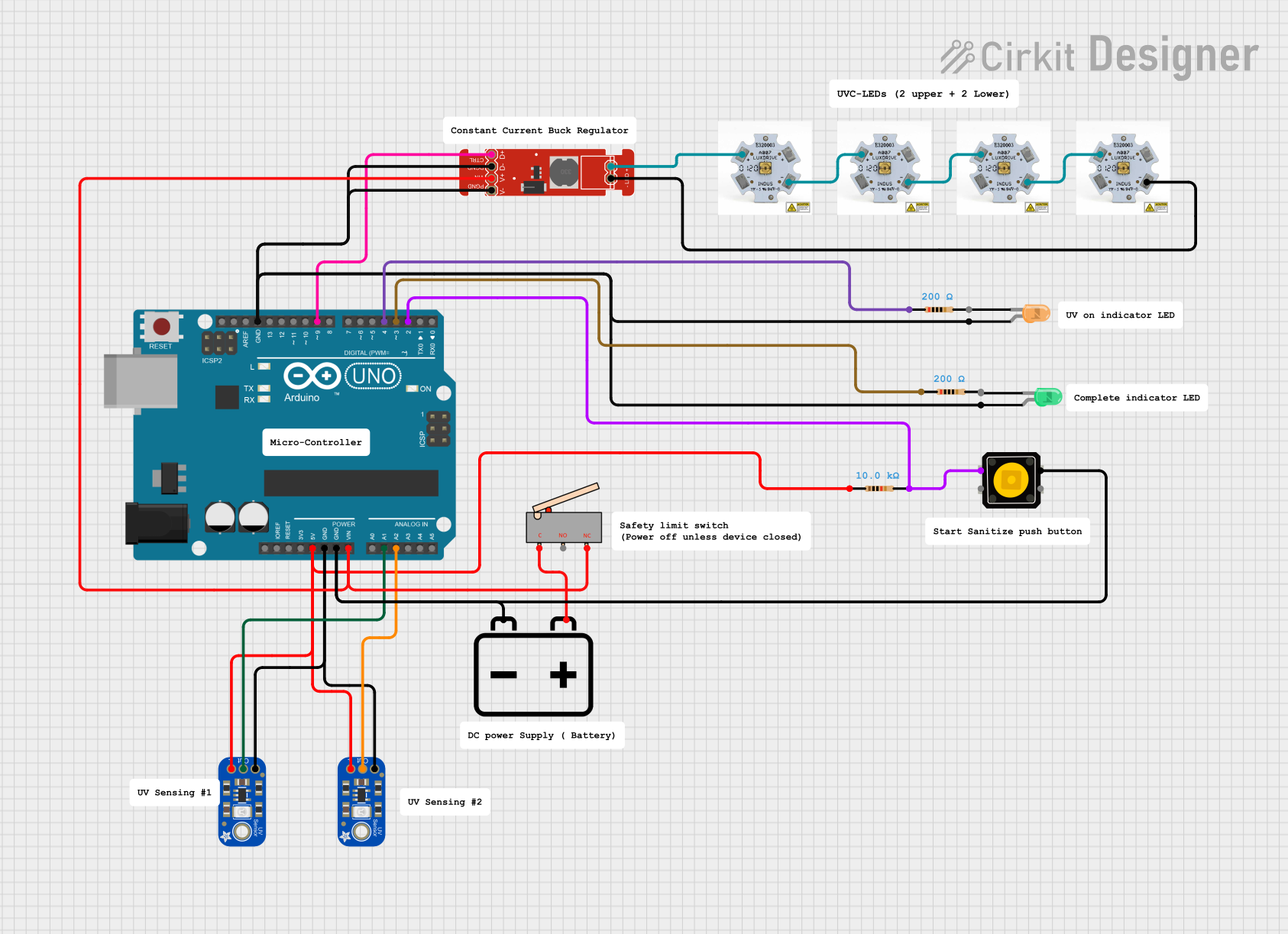
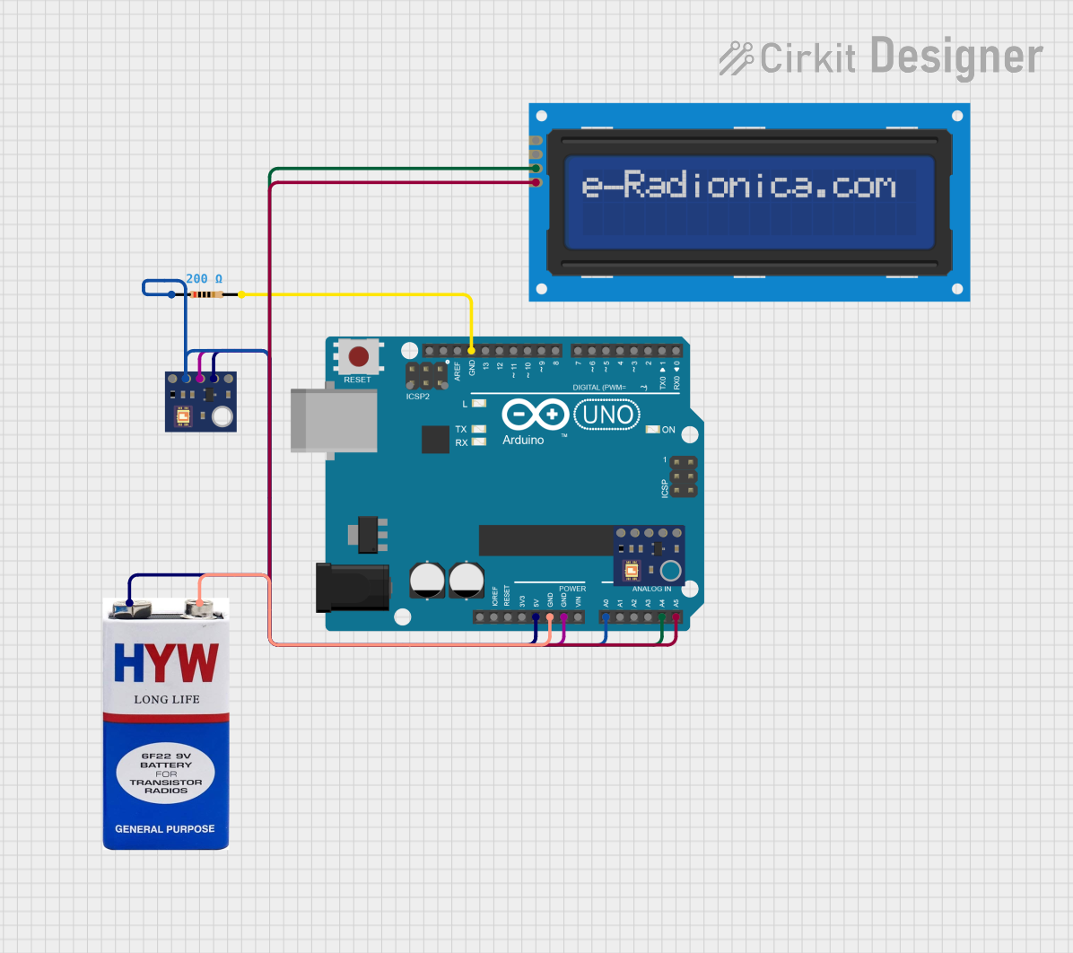
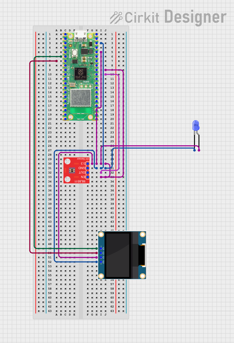
Explore Projects Built with Adafruit SI1145 Digital UV Index + IR + Visible Light Sensor
Common Applications and Use Cases
- UV Index monitoring for wearable devices
- Environmental monitoring for weather stations
- Light intensity measurements for smart lighting systems
- Proximity detection for objects or gestures
Technical Specifications
Key Technical Details
- UV Index Measurement Range: 0 to 11+
- IR Sensor Spectrum: Wavelengths from 700 nm to 1,100 nm
- Visible Light Sensor Spectrum: 550 nm (green light spectrum)
- Operating Voltage: 3.3V to 5V
- Interface: I2C
- I2C Address: 0x60 (default)
Pin Configuration and Descriptions
| Pin Number | Name | Description |
|---|---|---|
| 1 | VIN | Power supply (3.3V to 5V) |
| 2 | GND | Ground connection |
| 3 | SCL | I2C clock line |
| 4 | SDA | I2C data line |
| 5 | INT | Interrupt pin (active low) |
Usage Instructions
How to Use the Component in a Circuit
- Powering the Sensor: Connect the VIN pin to a 3.3V or 5V power supply and the GND pin to the ground.
- I2C Communication: Connect the SCL and SDA pins to the I2C clock and data lines on your microcontroller.
- Interrupts (Optional): The INT pin can be connected to a digital input on your microcontroller if you wish to use the interrupt feature.
Important Considerations and Best Practices
- Ensure that the power supply is within the specified voltage range to prevent damage.
- Use pull-up resistors on the I2C lines if they are not already present on your microcontroller board.
- Avoid exposing the sensor to direct sunlight for extended periods to prevent overheating and damage.
- When integrating with a microcontroller, ensure that the I2C library is compatible with the SI1145 sensor.
Example Code for Arduino UNO
#include <Wire.h>
#include "Adafruit_SI1145.h"

Adafruit_SI1145 uv = Adafruit_SI1145();

void setup() {
  Serial.begin(9600);
  if (!uv.begin()) {
    Serial.println("Didn't find Si1145");
    while (1);
  }
  Serial.println("Si1145 is ready!");
}

void loop() {
  Serial.println("===================");
  Serial.print("Vis: "); Serial.println(uv.readVisible());
  Serial.print("IR: "); Serial.println(uv.readIR());

  // Read UV index and divide by 100 to get the actual value
  Serial.print("UV: "); Serial.println(uv.readUV() / 100.0);
  delay(1000);
}
Troubleshooting and FAQs
Common Issues Users Might Face
- Sensor Not Detected: Ensure that the wiring is correct and that the sensor is properly powered.
- Inaccurate Readings: Check for obstructions or sources of light interference near the sensor.
- I2C Communication Errors: Verify that the correct I2C address is being used and that there are pull-up resistors on the I2C lines.
Solutions and Tips for Troubleshooting
- Double-check the connections and solder joints for any loose wires or cold solder points.
- Use a logic analyzer or oscilloscope to check the I2C signals if communication issues persist.
- Ensure that the sensor is not placed near heat sources or in direct sunlight for prolonged periods.
FAQs
Q: Can the SI1145 sensor measure UVB and UVC? A: The SI1145 is designed primarily to measure UVA and the UV Index, which is related to the effect of UVA and UVB on human skin. It does not measure UVC.
Q: Is calibration required for the SI1145 sensor? A: The sensor comes factory-calibrated for UV Index measurements. However, for precise applications, additional calibration against a known light source may be necessary.
Q: How can I use the interrupt feature? A: The INT pin can be used to trigger an interrupt on your microcontroller when certain light thresholds are reached. This requires additional programming to set up the interrupt thresholds and handle the interrupt signal.
Q: What is the maximum distance for reliable I2C communication with the SI1145? A: I2C is typically used for short-distance communication, usually not more than a meter. For longer distances, consider using I2C buffer or extender chips.