How to Use VSD_Squadron-mini: Examples, Pinouts, and Specs
Introduction
The VSD_Squadron-mini, manufactured by VSD, is a compact Variable Speed Drive (VSD) designed for precise control of electric motor speeds. This electronic component is essential in applications where motor speed regulation is critical, such as in conveyor systems, pumps, fans, and automated machinery. Its small size makes it ideal for integration into systems where space is at a premium.
Explore Projects Built with VSD_Squadron-mini

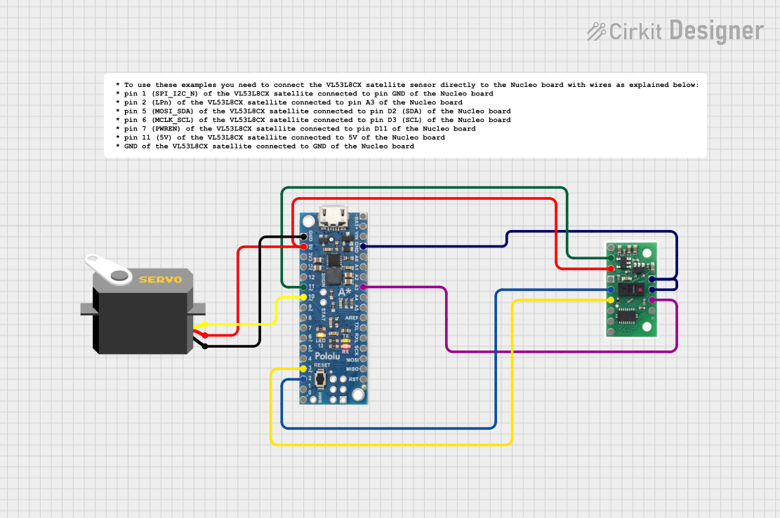
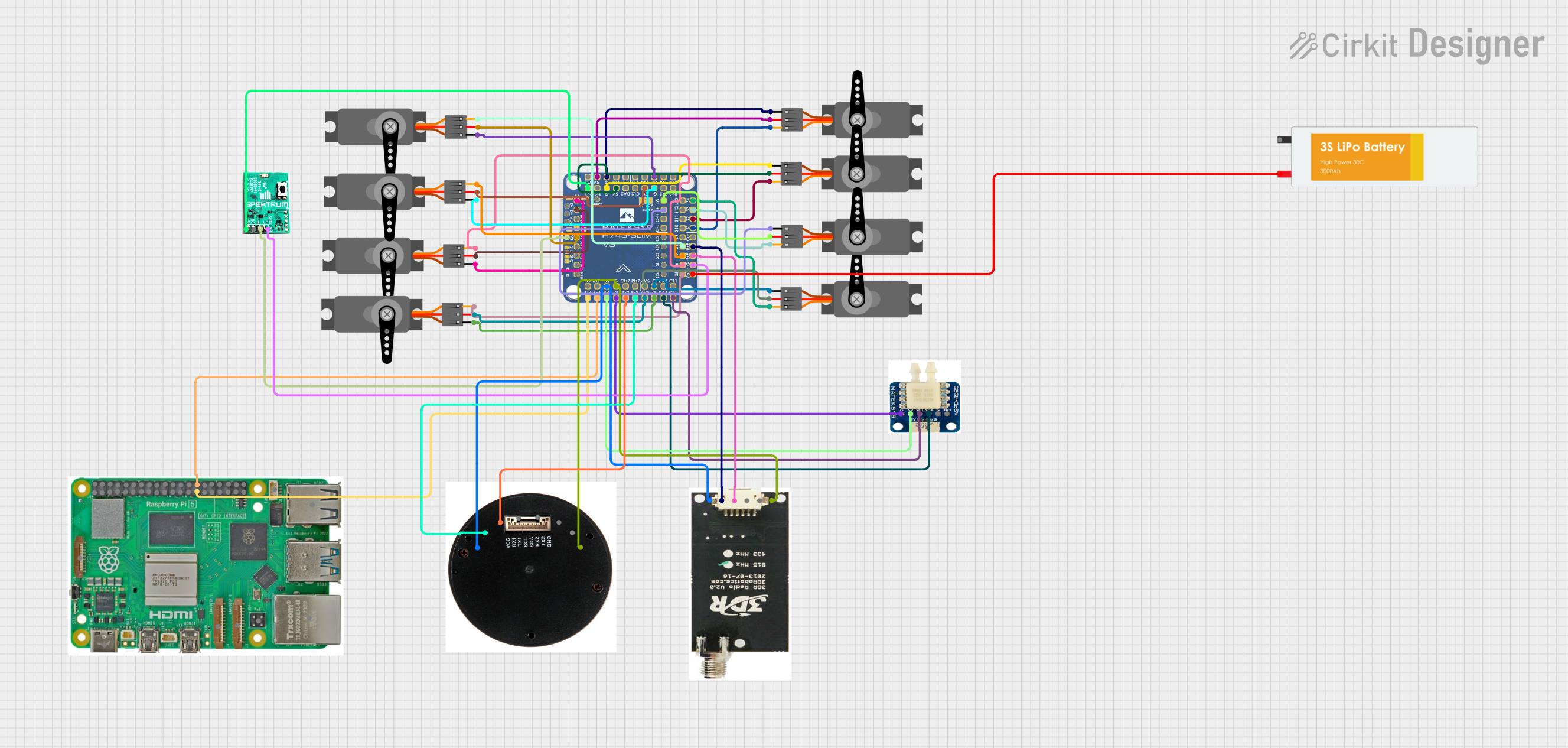
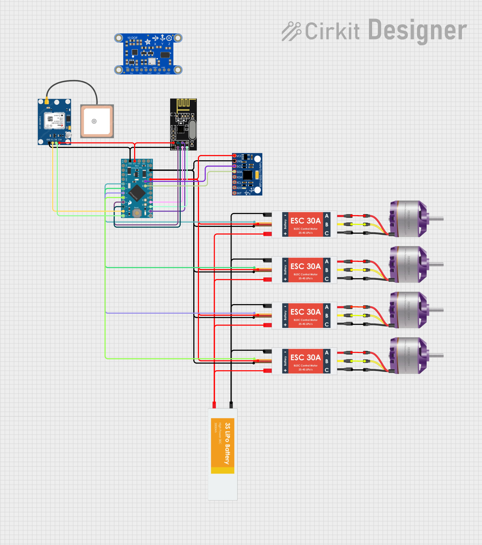
Explore Projects Built with VSD_Squadron-mini
Common Applications and Use Cases
- Industrial automation systems
- HVAC systems for controlling fan speeds
- Pump control for fluid management
- Speed control in conveyor belts
- Robotics and motion control systems
Technical Specifications
Key Technical Details
- Input Voltage: 110-240V AC
- Output Voltage: 0-230V AC (3-phase)
- Frequency Range: 0-400 Hz
- Power Ratings: Up to 2.2 kW
- Control Method: PWM (Pulse Width Modulation)
- Efficiency: >95%
- Operating Temperature: -10°C to +50°C
- Protection: Overcurrent, Overvoltage, Overtemperature, Short Circuit
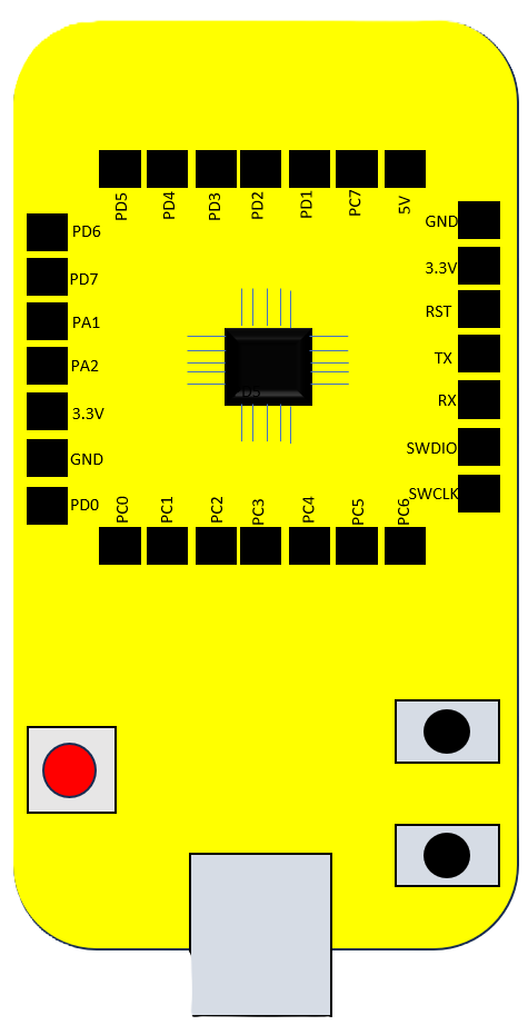
Pin Configuration and Descriptions
| Pin Number | Description | Notes |
|---|---|---|
| 1 | L1 (Phase 1 Input) | Connect to phase 1 of AC supply |
| 2 | L2 (Phase 2 Input) | Connect to phase 2 of AC supply |
| 3 | L3 (Phase 3 Input) | Connect to phase 3 of AC supply |
| 4 | U (Phase 1 Output to Motor) | Connect to motor phase 1 |
| 5 | V (Phase 2 Output to Motor) | Connect to motor phase 2 |
| 6 | W (Phase 3 Output to Motor) | Connect to motor phase 3 |
| 7 | GND (Ground) | Connect to system ground |
| 8 | Control Signal Input | Analog/Digital signal for control |
| 9 | Fault Output | Relay output for fault indication |
Usage Instructions
How to Use the Component in a Circuit
- Power Supply Connection: Connect the L1, L2, and L3 pins to the three-phase AC supply.
- Motor Connection: Connect the U, V, and W pins to the corresponding motor phases.
- Grounding: Ensure the GND pin is connected to the system ground to prevent electrical noise and potential damage.
- Control Signal: Apply the appropriate control signal to the Control Signal Input pin to regulate the motor speed.
Important Considerations and Best Practices
- Always ensure that the power supply matches the input specifications of the VSD_Squadron-mini.
- Use appropriate cable sizes to handle the current requirements of the motor.
- Install the VSD in a location with adequate ventilation to prevent overheating.
- Configure the VSD parameters according to the motor specifications for optimal performance.
- Ensure that all connections are secure to prevent accidental disconnection or electrical hazards.
Troubleshooting and FAQs
Common Issues Users Might Face
- Motor Not Starting: Check the power supply and connections. Ensure the control signal is correctly applied.
- Overheating: Verify that the VSD is not overloaded and that there is sufficient cooling.
- Unexpected Motor Behavior: Double-check the VSD parameter settings and adjust as necessary.
Solutions and Tips for Troubleshooting
- If the motor does not start, verify that the VSD is receiving power and that the control signal is within the specified range.
- In case of overheating, ensure that the ambient temperature is within the operating range and that the VSD has proper ventilation.
- For unexpected motor behavior, consult the VSD manual for parameter settings and ensure they match the motor's requirements.
FAQs
Q: Can the VSD_Squadron-mini be used with single-phase motors? A: No, it is designed for three-phase motors only.
Q: What should I do if I receive a fault indication? A: Check the fault code in the manual and follow the recommended troubleshooting steps.
Q: Is it possible to control the VSD remotely? A: Yes, you can control the VSD remotely by connecting the control signal input to a remote control system.
Q: How do I ensure the longevity of the VSD? A: Regular maintenance, proper installation, and adherence to the operating conditions will ensure the longevity of the VSD.
Code Example for Arduino UNO Integration
// Example code to control VSD_Squadron-mini using Arduino UNO
#include <SoftwareSerial.h>

SoftwareSerial vsdSerial(10, 11); // RX, TX

void setup() {
  // Start serial communication with VSD at 9600 baud rate
  vsdSerial.begin(9600);
}

void loop() {
  // Example: Set VSD speed to 50% using a control signal
  int speedValue = 128; // Speed value ranges from 0 to 255 (0-100%)
  vsdSerial.write(speedValue);

  // Add your code here to adjust speed based on your application needs

  delay(1000); // Delay for demonstration purposes
}
Note: The above code is a simple demonstration of how to send a control signal to the VSD_Squadron-mini using an Arduino UNO. The actual implementation may vary based on the specific control protocol of the VSD. Always refer to the VSD's technical manual for the correct control signal format and communication protocol.