How to Use ESP32 (30 pin, Sized correctly): Examples, Pinouts, and Specs
Introduction
The ESP32, manufactured by Espressif, is a powerful microcontroller that integrates built-in Wi-Fi and Bluetooth capabilities. With its 30-pin configuration, it offers versatile connectivity and is ideal for a wide range of electronic projects. The ESP32 is widely used in IoT (Internet of Things) applications, home automation, robotics, and wireless communication systems due to its high performance, low power consumption, and extensive peripheral support.
Explore Projects Built with ESP32 (30 pin, Sized correctly)


Explore Projects Built with ESP32 (30 pin, Sized correctly)
Common Applications and Use Cases
- IoT devices and smart home systems
- Wireless sensor networks
- Robotics and automation
- Wearable devices
- Data logging and remote monitoring
- Bluetooth-enabled applications
- Real-time audio and video streaming
Technical Specifications
The ESP32 (30-pin version) is designed to provide robust performance and flexibility. Below are its key technical details:
Key Technical Details
| Parameter | Specification |
|---|---|
| Microcontroller | Tensilica Xtensa LX6 dual-core (or single-core) |
| Clock Speed | Up to 240 MHz |
| Flash Memory | 4 MB (varies by model) |
| SRAM | 520 KB |
| Wi-Fi | 802.11 b/g/n |
| Bluetooth | v4.2 BR/EDR and BLE |
| Operating Voltage | 3.3V |
| Input Voltage Range | 5V (via USB) or 3.3V (via VIN pin) |
| GPIO Pins | 30 |
| ADC Channels | 18 |
| DAC Channels | 2 |
| Communication Interfaces | UART, SPI, I2C, I2S, CAN, PWM |
| Power Consumption | Ultra-low power (varies by mode) |
| Operating Temperature | -40°C to +85°C |
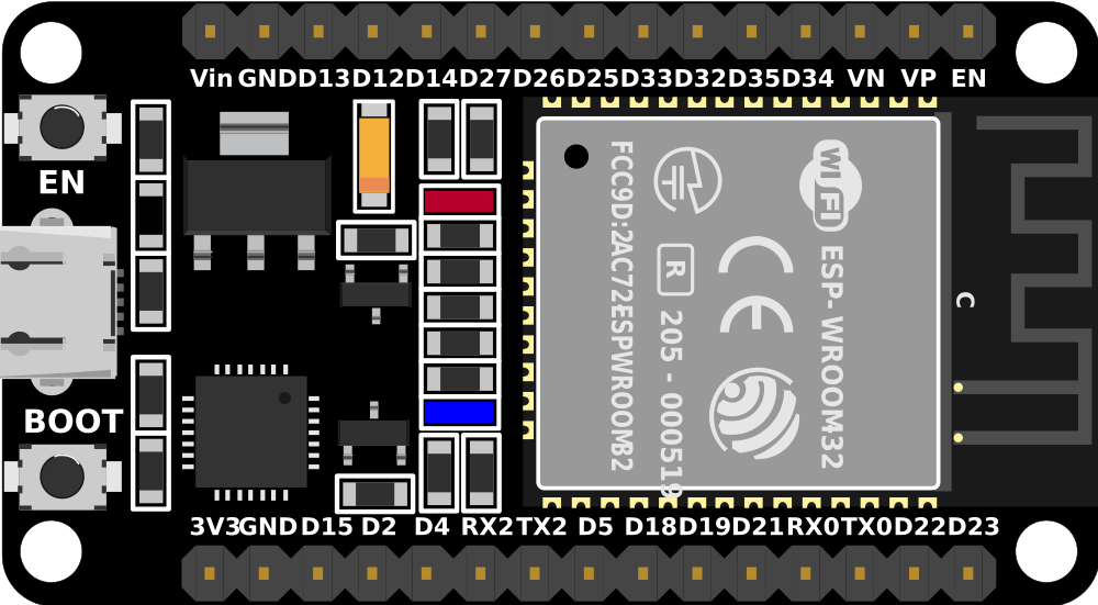
Pin Configuration and Descriptions
The ESP32 (30-pin version) has a standard pinout for easy interfacing. Below is the pin configuration:
| Pin Number | Pin Name | Description |
|---|---|---|
| 1 | EN | Enable pin (active high, resets the chip) |
| 2 | IO0 | GPIO0, used for boot mode selection |
| 3 | IO1 (TX0) | GPIO1, UART0 TX (serial communication) |
| 4 | IO3 (RX0) | GPIO3, UART0 RX (serial communication) |
| 5 | IO4 | GPIO4, general-purpose I/O |
| 6 | IO5 | GPIO5, general-purpose I/O |
| 7 | GND | Ground |
| 8 | VIN | Power input (5V) |
| 9 | IO12 | GPIO12, general-purpose I/O |
| 10 | IO13 | GPIO13, general-purpose I/O |
| 11 | IO14 | GPIO14, general-purpose I/O |
| 12 | IO15 | GPIO15, general-purpose I/O |
| 13 | IO16 | GPIO16, general-purpose I/O |
| 14 | IO17 | GPIO17, general-purpose I/O |
| 15 | IO18 | GPIO18, general-purpose I/O |
| 16 | IO19 | GPIO19, general-purpose I/O |
| 17 | IO21 | GPIO21, general-purpose I/O |
| 18 | IO22 | GPIO22, general-purpose I/O |
| 19 | IO23 | GPIO23, general-purpose I/O |
| 20 | GND | Ground |
| 21 | IO25 | GPIO25, DAC1 |
| 22 | IO26 | GPIO26, DAC2 |
| 23 | IO27 | GPIO27, general-purpose I/O |
| 24 | IO32 | GPIO32, ADC1 Channel 4 |
| 25 | IO33 | GPIO33, ADC1 Channel 5 |
| 26 | IO34 | GPIO34, ADC1 Channel 6 (input only) |
| 27 | IO35 | GPIO35, ADC1 Channel 7 (input only) |
| 28 | 3V3 | 3.3V power output |
| 29 | GND | Ground |
| 30 | IO2 | GPIO2, general-purpose I/O |
Usage Instructions
The ESP32 is highly versatile and can be used in a variety of circuits. Below are the steps and best practices for using the ESP32 in your projects.
How to Use the ESP32 in a Circuit
Powering the ESP32:
- Use a 5V power supply via the VIN pin or USB connection.
- Ensure the power source can provide sufficient current (at least 500 mA).
Connecting to Peripherals:
- Use GPIO pins for digital input/output.
- Use ADC pins for analog input (e.g., sensors).
- Use UART, SPI, or I2C for communication with other devices.
Programming the ESP32:
- Install the ESP32 board package in the Arduino IDE or use Espressif's ESP-IDF.
- Connect the ESP32 to your computer via USB.
- Select the correct board and port in the IDE.
- Write and upload your code.
Example Code for Arduino IDE
The following example demonstrates how to blink an LED connected to GPIO2:
// Blink an LED connected to GPIO2 on the ESP32

#define LED_PIN 2  // Define the GPIO pin for the LED

void setup() {
  pinMode(LED_PIN, OUTPUT);  // Set GPIO2 as an output pin
}

void loop() {
  digitalWrite(LED_PIN, HIGH);  // Turn the LED on
  delay(1000);                  // Wait for 1 second
  digitalWrite(LED_PIN, LOW);   // Turn the LED off
  delay(1000);                  // Wait for 1 second
}
Important Considerations and Best Practices
- Voltage Levels: Ensure all connected peripherals operate at 3.3V logic levels to avoid damaging the ESP32.
- Boot Mode: GPIO0 must be pulled low during boot to enter programming mode.
- Power Supply: Use a stable power source to prevent unexpected resets or malfunctions.
- Wi-Fi and Bluetooth: Avoid placing the ESP32 near metal objects or enclosures that may interfere with wireless signals.
Troubleshooting and FAQs
Common Issues and Solutions
ESP32 Not Detected by Computer:
- Ensure the correct USB driver is installed (e.g., CP210x or CH340).
- Check the USB cable for damage or try a different cable.
Upload Fails with Timeout Error:
- Press and hold the "BOOT" button on the ESP32 while uploading the code.
- Verify the correct board and port are selected in the IDE.
Wi-Fi Connection Issues:
- Check the SSID and password in your code.
- Ensure the router is within range and supports 2.4 GHz Wi-Fi.
Random Resets or Instability:
- Use a power supply with sufficient current capacity.
- Add decoupling capacitors near the power pins.
FAQs
Q: Can the ESP32 operate on battery power?
A: Yes, the ESP32 can be powered by a LiPo battery connected to the VIN pin. Use a voltage regulator if necessary.
Q: How do I use the ESP32's Bluetooth functionality?
A: The ESP32 supports both Bluetooth Classic and BLE. Use the Arduino IDE or ESP-IDF libraries to implement Bluetooth communication.
Q: Can I use the ESP32 with 5V peripherals?
A: No, the ESP32 operates at 3.3V logic levels. Use a level shifter to interface with 5V devices.
Q: How do I reset the ESP32?
A: Press the "EN" button on the board to reset the ESP32.
By following this documentation, you can effectively use the ESP32 in your projects and troubleshoot common issues.