
Cirkit Designer
Your all-in-one circuit design IDE
Home /
Component Documentation
How to Use Seeed Studio XIAO ESP32C6: Examples, Pinouts, and Specs
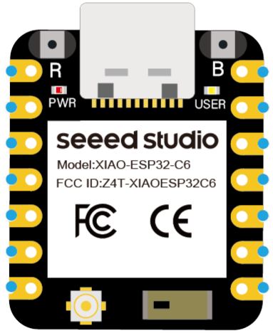
 Design with Seeed Studio XIAO ESP32C6 in Cirkit Designer
Introduction
The Seeed Studio XIAO ESP32C6 is a compact microcontroller board featuring the ESP32-C6 chip. This board supports Wi-Fi 6 and Bluetooth 5.0, making it an excellent choice for IoT applications that require low power consumption and high performance. Its small form factor and robust capabilities make it ideal for a wide range of projects, from home automation to wearable devices.
Explore Projects Built with Seeed Studio XIAO ESP32C6
ESP32-C6 and ST7735S Display: Wi-Fi Controlled TFT Display Module
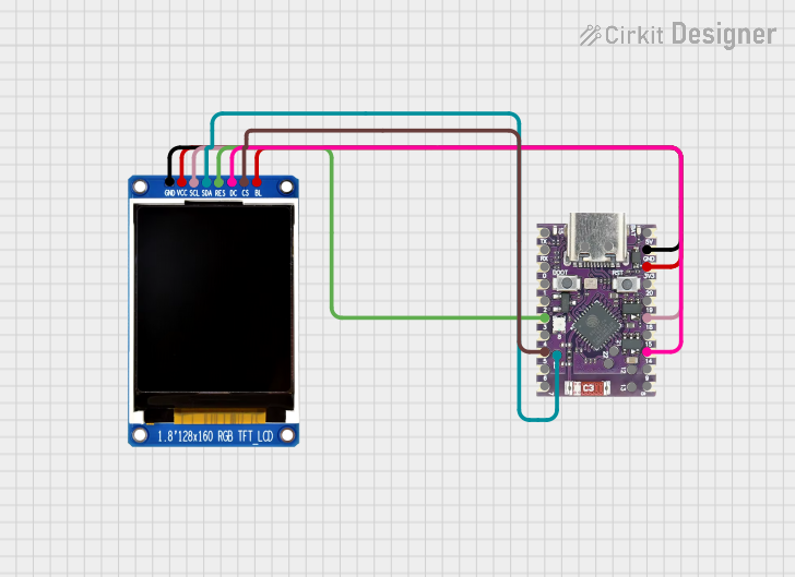
This circuit features an ESP32-C6 microcontroller interfaced with a China ST7735S 160x128 TFT display. The ESP32-C6 controls the display via SPI communication, providing power, ground, and control signals to render graphics and text on the screen.
 Open Project in Cirkit Designer
ESP32-Based Multi-Sensor Health Monitoring System with Bluetooth Connectivity
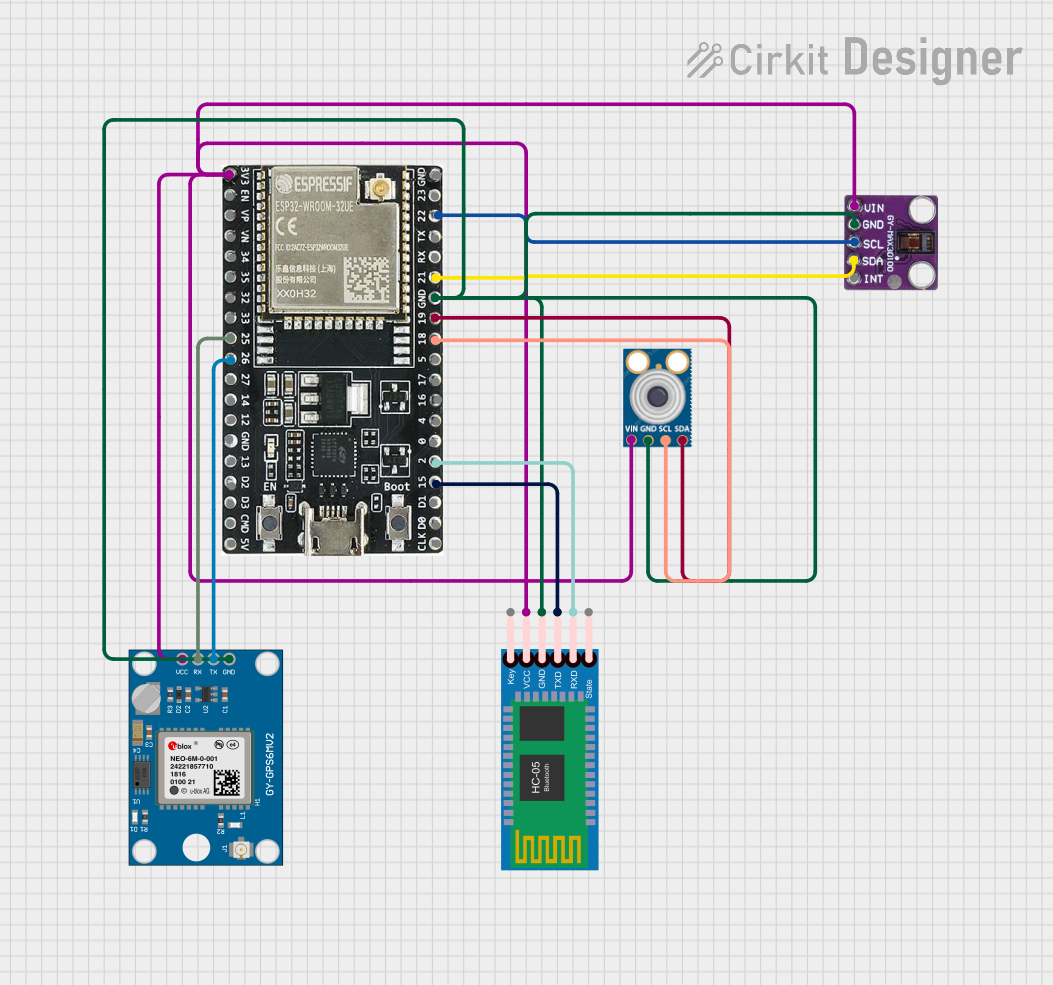
This circuit features an ESP32-WROOM-32UE microcontroller as the central processing unit, interfacing with a variety of sensors and modules. It includes a MAX30100 pulse oximeter and heart-rate sensor, an MLX90614 infrared thermometer, an HC-05 Bluetooth module for wireless communication, and a Neo 6M GPS module for location tracking. All components are powered by a common voltage supply and are connected to specific GPIO pins on the ESP32 for data exchange, with the sensors using I2C communication and the modules using UART.
 Open Project in Cirkit Designer
Xiao ESP32 C3 Based Temperature and Humidity Monitoring System
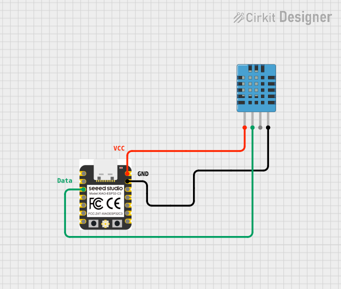
This circuit features a Xiao ESP32 C3 microcontroller connected to a DHT11 Humidity and Temperature Sensor. The ESP32 C3 provides power to the DHT11 sensor through its VUSB pin and receives data from the sensor's DATA pin via the ESP32's D2 pin. The circuit is designed to measure environmental temperature and humidity, with the microcontroller processing and potentially communicating the sensor data.
 Open Project in Cirkit Designer
ESP32-Based LoRa Communication Device with OLED Display
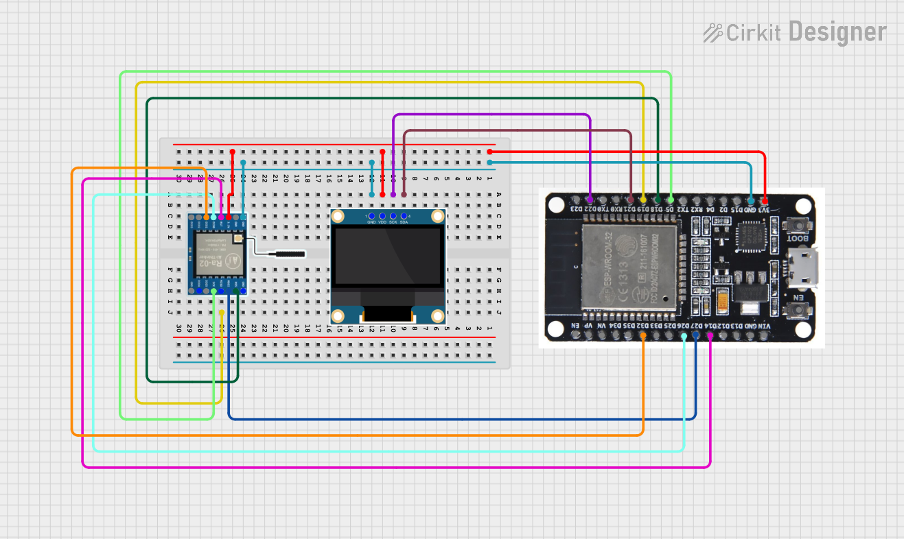
This circuit features an ESP32 microcontroller connected to a 0.96" OLED display and a LoRa Ra-02 SX1278 module for wireless communication. The ESP32 facilitates communication with the OLED display via I2C (SDA and SCK lines) and with the LoRa module via SPI (MISO, MOSI, SCK, NSS lines) and GPIO for control signals (DI00, DI01, RST). The circuit is designed for applications requiring wireless data transmission and visual data display.
 Open Project in Cirkit Designer
Explore Projects Built with Seeed Studio XIAO ESP32C6

ESP32-C6 and ST7735S Display: Wi-Fi Controlled TFT Display Module
This circuit features an ESP32-C6 microcontroller interfaced with a China ST7735S 160x128 TFT display. The ESP32-C6 controls the display via SPI communication, providing power, ground, and control signals to render graphics and text on the screen.
 Open Project in Cirkit Designer
ESP32-Based Multi-Sensor Health Monitoring System with Bluetooth Connectivity
This circuit features an ESP32-WROOM-32UE microcontroller as the central processing unit, interfacing with a variety of sensors and modules. It includes a MAX30100 pulse oximeter and heart-rate sensor, an MLX90614 infrared thermometer, an HC-05 Bluetooth module for wireless communication, and a Neo 6M GPS module for location tracking. All components are powered by a common voltage supply and are connected to specific GPIO pins on the ESP32 for data exchange, with the sensors using I2C communication and the modules using UART.
 Open Project in Cirkit Designer
Xiao ESP32 C3 Based Temperature and Humidity Monitoring System
This circuit features a Xiao ESP32 C3 microcontroller connected to a DHT11 Humidity and Temperature Sensor. The ESP32 C3 provides power to the DHT11 sensor through its VUSB pin and receives data from the sensor's DATA pin via the ESP32's D2 pin. The circuit is designed to measure environmental temperature and humidity, with the microcontroller processing and potentially communicating the sensor data.
 Open Project in Cirkit Designer
ESP32-Based LoRa Communication Device with OLED Display
This circuit features an ESP32 microcontroller connected to a 0.96" OLED display and a LoRa Ra-02 SX1278 module for wireless communication. The ESP32 facilitates communication with the OLED display via I2C (SDA and SCK lines) and with the LoRa module via SPI (MISO, MOSI, SCK, NSS lines) and GPIO for control signals (DI00, DI01, RST). The circuit is designed for applications requiring wireless data transmission and visual data display.
 Open Project in Cirkit Designer
Common Applications and Use Cases
- IoT Devices: Smart home systems, environmental monitoring, and industrial IoT.
- Wearable Technology: Fitness trackers, health monitoring devices.
- Wireless Communication: Wi-Fi and Bluetooth-enabled projects.
- Prototyping and Development: Rapid development of connected devices.
Technical Specifications
Key Technical Details
| Specification | Value |
|---|---|
| Microcontroller | ESP32-C6 |
| Wi-Fi | Wi-Fi 6 (802.11ax) |
| Bluetooth | Bluetooth 5.0 |
| Operating Voltage | 3.3V |
| Input Voltage | 5V (via USB) |
| Digital I/O Pins | 11 |
| Analog Input Pins | 6 (12-bit ADC) |
| Flash Memory | 4MB |
| SRAM | 512KB |
| Dimensions | 21 x 17.5 mm |
Pin Configuration and Descriptions
| Pin Number | Pin Name | Description |
|---|---|---|
| 1 | 3V3 | 3.3V Power Output |
| 2 | GND | Ground |
| 3 | D0 | Digital I/O Pin 0 |
| 4 | D1 | Digital I/O Pin 1 |
| 5 | D2 | Digital I/O Pin 2 |
| 6 | D3 | Digital I/O Pin 3 |
| 7 | D4 | Digital I/O Pin 4 |
| 8 | D5 | Digital I/O Pin 5 |
| 9 | D6 | Digital I/O Pin 6 |
| 10 | D7 | Digital I/O Pin 7 |
| 11 | D8 | Digital I/O Pin 8 |
| 12 | D9 | Digital I/O Pin 9 |
| 13 | D10 | Digital I/O Pin 10 |
| 14 | A0 | Analog Input Pin 0 |
| 15 | A1 | Analog Input Pin 1 |
| 16 | A2 | Analog Input Pin 2 |
| 17 | A3 | Analog Input Pin 3 |
| 18 | A4 | Analog Input Pin 4 |
| 19 | A5 | Analog Input Pin 5 |
| 20 | RX | UART Receive Pin |
| 21 | TX | UART Transmit Pin |
| 22 | SCL | I2C Clock Pin |
| 23 | SDA | I2C Data Pin |
Usage Instructions
How to Use the Component in a Circuit
Powering the Board:
- Connect the 5V input to a USB power source.
- Ensure the 3.3V pin is used for powering external components if needed.
Connecting to Wi-Fi:
- Use the built-in Wi-Fi 6 capabilities to connect to a network.
- Example code for connecting to Wi-Fi is provided below.
Using Digital and Analog Pins:
- Digital pins can be used for input or output.
- Analog pins can read sensor data with a 12-bit resolution.
Important Considerations and Best Practices
- Power Supply: Ensure a stable 5V power supply to avoid damage.
- Pin Usage: Avoid using pins for both digital and analog functions simultaneously.
- Heat Management: Although the board is designed for low power consumption, ensure proper ventilation if used in enclosed spaces.
Example Code for Connecting to Wi-Fi
#include <WiFi.h>

// Replace with your network credentials
const char* ssid = "your_SSID";
const char* password = "your_PASSWORD";

void setup() {
  Serial.begin(115200);
  delay(10);

  // Connect to Wi-Fi
  Serial.println();
  Serial.print("Connecting to ");
  Serial.println(ssid);

  WiFi.begin(ssid, password);

  while (WiFi.status() != WL_CONNECTED) {
    delay(500);
    Serial.print(".");
  }

  Serial.println("");
  Serial.println("WiFi connected.");
  Serial.println("IP address: ");
  Serial.println(WiFi.localIP());
}

void loop() {
  // Your code here
}
Troubleshooting and FAQs
Common Issues Users Might Face
Wi-Fi Connection Issues:
- Ensure the SSID and password are correct.
- Check if the router is within range.
Power Supply Problems:
- Verify the USB cable and power source.
- Ensure the 3.3V pin is not overloaded.
Pin Configuration Errors:
- Double-check the pin connections.
- Ensure no pins are shorted.
Solutions and Tips for Troubleshooting
Wi-Fi Connection:
- Restart the router and the XIAO ESP32C6 board.
- Use a Wi-Fi analyzer to check for interference.
Power Supply:
- Use a different USB cable or power adapter.
- Measure the voltage at the 3.3V pin to ensure it is stable.
Pin Configuration:
- Use a multimeter to check for continuity.
- Refer to the pin configuration table to ensure correct connections.
By following this documentation, users can effectively utilize the Seeed Studio XIAO ESP32C6 in their projects, ensuring optimal performance and reliability.