How to Use Kyber Controller: Examples, Pinouts, and Specs
Introduction
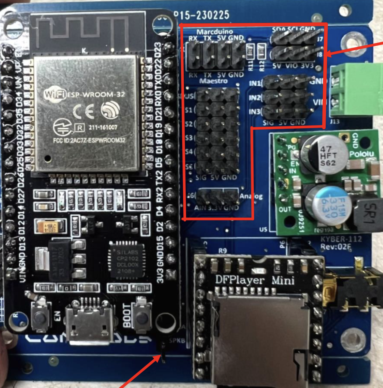
The Kyber Controller (KYBER112), manufactured by Kyber Robotics, is a versatile microcontroller designed for managing and controlling various electronic systems. It is particularly well-suited for robotics and automation applications, offering robust performance, flexible interfacing options, and ease of integration into complex systems. With its advanced processing capabilities and multiple I/O options, the Kyber Controller is ideal for tasks such as motor control, sensor data processing, and communication with other devices.
Explore Projects Built with Kyber Controller

Explore Projects Built with Kyber Controller
Common Applications and Use Cases
- Robotics control systems
- Industrial automation
- IoT (Internet of Things) devices
- Motor and actuator control
- Sensor data acquisition and processing
- Home automation systems
Technical Specifications
The Kyber Controller is built to handle a wide range of tasks with efficiency and reliability. Below are its key technical specifications:
| Parameter | Specification |
|---|---|
| Manufacturer | Kyber Robotics |
| Part ID | KYBER112 |
| Operating Voltage | 3.3V to 5V |
| Maximum Current | 500mA |
| Clock Speed | 48 MHz |
| Flash Memory | 256 KB |
| SRAM | 32 KB |
| GPIO Pins | 20 (Digital: 14, Analog: 6) |
| Communication Interfaces | UART, I2C, SPI |
| PWM Channels | 6 |
| Operating Temperature | -40°C to 85°C |
| Dimensions | 35mm x 25mm |
Pin Configuration and Descriptions
The Kyber Controller features a total of 20 pins, including digital, analog, and power pins. Below is the pin configuration:
| Pin Number | Pin Name | Type | Description |
|---|---|---|---|
| 1 | VIN | Power | Input voltage (3.3V to 5V) |
| 2 | GND | Power | Ground |
| 3 | D0/RX | Digital (UART) | UART Receive |
| 4 | D1/TX | Digital (UART) | UART Transmit |
| 5 | D2 | Digital | General-purpose digital I/O |
| 6 | D3 (PWM) | Digital (PWM) | PWM-capable digital I/O |
| 7 | D4 | Digital | General-purpose digital I/O |
| 8 | D5 (PWM) | Digital (PWM) | PWM-capable digital I/O |
| 9 | D6 (PWM) | Digital (PWM) | PWM-capable digital I/O |
| 10 | D7 | Digital | General-purpose digital I/O |
| 11 | D8 | Digital | General-purpose digital I/O |
| 12 | D9 (PWM) | Digital (PWM) | PWM-capable digital I/O |
| 13 | D10 (PWM) | Digital (PWM) | PWM-capable digital I/O |
| 14 | A0 | Analog | Analog input (10-bit resolution) |
| 15 | A1 | Analog | Analog input (10-bit resolution) |
| 16 | A2 | Analog | Analog input (10-bit resolution) |
| 17 | A3 | Analog | Analog input (10-bit resolution) |
| 18 | A4 (SDA) | Analog/I2C | Analog input or I2C data line |
| 19 | A5 (SCL) | Analog/I2C | Analog input or I2C clock line |
| 20 | RESET | Control | Resets the microcontroller |
Usage Instructions
The Kyber Controller is easy to integrate into a variety of electronic systems. Below are the steps and best practices for using the component:
How to Use the Kyber Controller in a Circuit
- Powering the Controller: Connect the VIN pin to a 3.3V or 5V power source and the GND pin to ground.
- Connecting Peripherals:
- Use the digital pins (D0-D13) for interfacing with digital devices such as LEDs, switches, or relays.
- Use the analog pins (A0-A5) for reading sensor data or other analog signals.
- For PWM control, use the PWM-capable pins (D3, D5, D6, D9, D10).
- Communication:
- Use the UART pins (D0/RX and D1/TX) for serial communication.
- Use the I2C pins (A4/SDA and A5/SCL) for interfacing with I2C devices.
- Use the SPI interface for high-speed communication with compatible devices.
- Programming: The Kyber Controller can be programmed using standard microcontroller development tools or platforms like Arduino IDE.
Important Considerations and Best Practices
- Ensure the input voltage does not exceed the specified range (3.3V to 5V) to avoid damaging the controller.
- Use appropriate pull-up or pull-down resistors for input pins to prevent floating states.
- When using PWM pins, ensure the connected devices can handle the PWM frequency and voltage levels.
- For I2C communication, use pull-up resistors (typically 4.7kΩ) on the SDA and SCL lines.
Example Code for Arduino UNO
Below is an example of how to use the Kyber Controller with an Arduino UNO to blink an LED connected to pin D3:
// Define the pin for the LED
const int ledPin = 3; // D3 is a PWM-capable pin

void setup() {
  pinMode(ledPin, OUTPUT); // Set the LED pin as an output
}

void loop() {
  digitalWrite(ledPin, HIGH); // Turn the LED on
  delay(1000);               // Wait for 1 second
  digitalWrite(ledPin, LOW);  // Turn the LED off
  delay(1000);               // Wait for 1 second
}
Troubleshooting and FAQs
Common Issues Users Might Face
The controller does not power on:
- Ensure the VIN pin is connected to a stable power source within the specified voltage range.
- Check for loose or incorrect connections.
Unable to upload code to the controller:
- Verify that the correct COM port and board type are selected in the programming software.
- Ensure the USB cable is functional and properly connected.
I2C devices are not responding:
- Check the pull-up resistors on the SDA and SCL lines.
- Verify the I2C address of the connected device.
PWM output is not working:
- Ensure the connected device supports PWM signals.
- Verify that the correct PWM pin is being used.
Solutions and Tips for Troubleshooting
- Use a multimeter to check voltage levels and continuity in the circuit.
- Refer to the Kyber Controller datasheet for detailed electrical characteristics.
- If the controller becomes unresponsive, try pressing the RESET pin to restart it.
By following this documentation, users can effectively integrate and utilize the Kyber Controller (KYBER112) in their projects.