Cirkit Designer LogoCirkit DesignerYour all-in-one circuit design IDE Launch Cirkit Designer App

How to Use Wireless Charging Module Transmitter: Examples, Pinouts, and Specs

Image of Wireless Charging Module TransmitterDesign with Wireless Charging Module Transmitter in Cirkit Designer

Introduction

The Wireless Charging Module Transmitter CC1 is a device designed to transmit power wirelessly to compatible receivers using electromagnetic induction. This module eliminates the need for physical connectors, enabling convenient and efficient charging for a variety of devices. It is commonly used in applications such as wireless phone chargers, wearable device chargers, and other consumer electronics requiring contactless power transfer.

Explore Projects Built with Wireless Charging Module Transmitter

Use Cirkit Designer to design, explore, and prototype these projects online. Some projects support real-time simulation. Click "Open Project" to start designing instantly!
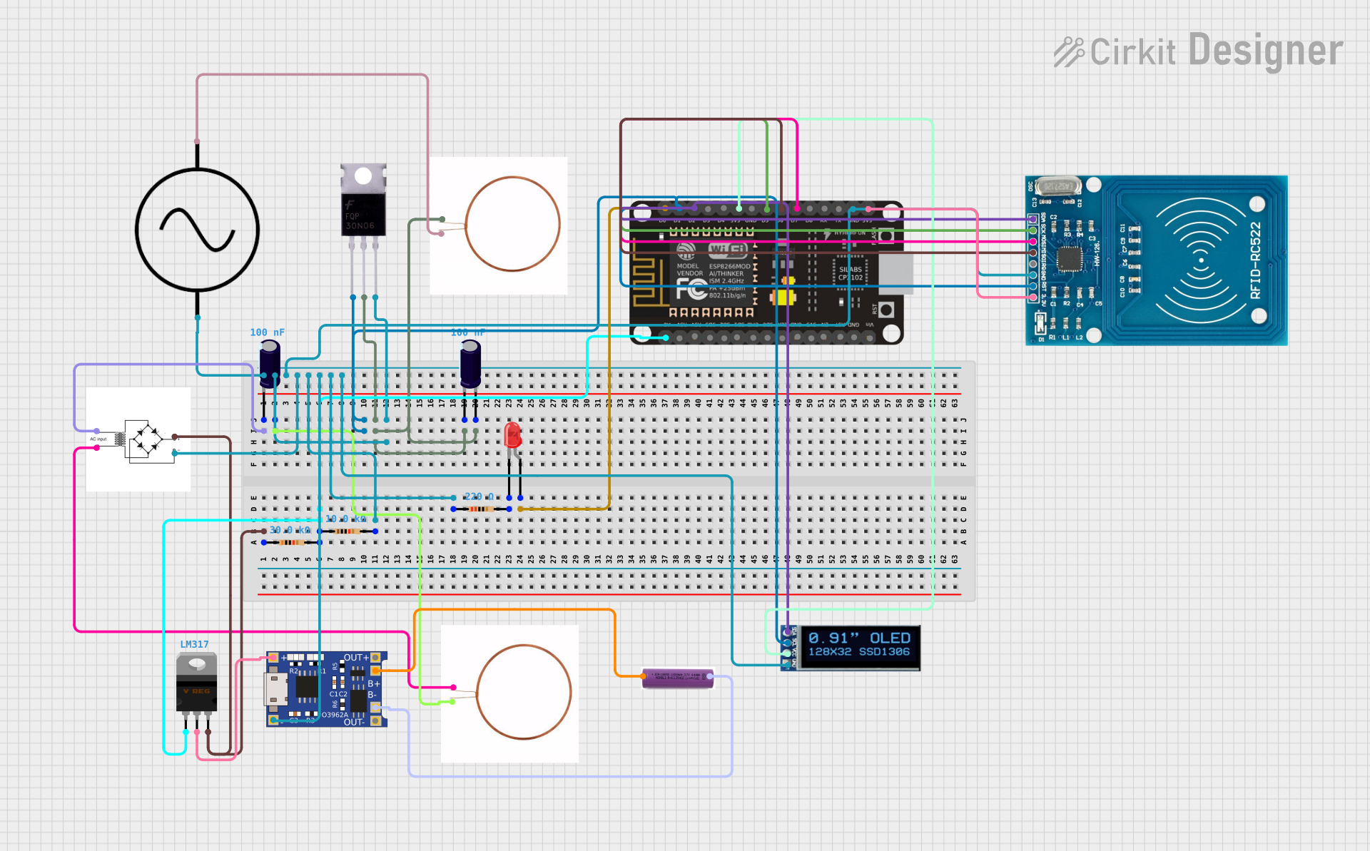
Image of ESP8266-Controlled Wireless EV Charging System with RFID Authentication: A project utilizing Wireless Charging Module Transmitter in a practical application

ESP8266-Controlled Wireless EV Charging System with RFID Authentication

This circuit appears to be a wireless charging system with RFID access control, powered by an AC supply that is rectified and regulated. It includes an ESP8266 microcontroller for managing the charging process and displaying status information on an OLED display. The RFID-RC522 module is used to authorize the charging process, and a MOSFET is likely used to control the power to the charging coil.

Open Project in Cirkit Designer
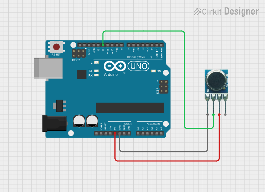
Image of Arduino UNO Controlled 433MHz RF Transmitter: A project utilizing Wireless Charging Module Transmitter in a practical application
Arduino UNO Controlled 433MHz RF Transmitter

This circuit consists of an Arduino UNO microcontroller connected to a 433MHz RF Transmitter module. The Arduino provides power to the RF Transmitter and is likely to control it via digital pin D12. The purpose of this circuit is to enable wireless communication, with the Arduino controlling the transmission of data through the RF module.

Open Project in Cirkit Designer

Common Applications:

Technical Specifications

Key Technical Details:

Parameter Value
Input Voltage 5V DC
Input Current 1A
Output Power Up to 5W
Transmission Frequency 110-205 kHz
Efficiency ~70%
Operating Temperature -10°C to 50°C
Dimensions 30mm x 20mm x 5mm

Pin Configuration and Descriptions:

Pin Name Pin Type Description
VCC Power Input Connect to a 5V DC power source.
GND Ground Connect to the ground of the power source.
OUT+ Output Signal Positive output terminal for the wireless transmission coil.
OUT- Output Signal Negative output terminal for the wireless transmission coil.

Usage Instructions

How to Use the Wireless Charging Module Transmitter CC1:

  1. Power Supply Connection:

    • Connect the VCC pin to a stable 5V DC power source.
    • Connect the GND pin to the ground of the power source.
  2. Coil Connection:

    • Attach the wireless transmission coil to the OUT+ and OUT- pins. Ensure proper polarity.
  3. Placement:

    • Place the compatible wireless receiver device (e.g., a smartphone or receiver module) within the effective charging range (typically 2-8mm) of the transmission coil.
  4. Operation:

    • Once powered, the module will generate an electromagnetic field to transfer power wirelessly to the receiver.

Important Considerations:

Example: Using with an Arduino UNO

While the CC1 module does not directly interface with an Arduino, you can use an Arduino to control the power supply to the module. Below is an example of how to toggle the power to the module using a relay:

// Example: Controlling the Wireless Charging Module with Arduino
// This code toggles the power to the CC1 module using a relay module.

const int relayPin = 7; // Pin connected to the relay module

void setup() {
  pinMode(relayPin, OUTPUT); // Set relay pin as output
  digitalWrite(relayPin, LOW); // Ensure relay is off at startup
}

void loop() {
  digitalWrite(relayPin, HIGH); // Turn on the relay (power to CC1)
  delay(10000); // Keep the module on for 10 seconds
  digitalWrite(relayPin, LOW); // Turn off the relay (cut power to CC1)
  delay(5000); // Wait for 5 seconds before turning it on again
}

Note: Ensure the relay module is rated for the input voltage and current of the CC1 module.

Troubleshooting and FAQs

Common Issues and Solutions:

  1. No Power Transmission:

    • Cause: Incorrect power supply connection.
    • Solution: Verify that the VCC and GND pins are properly connected to a 5V DC power source.
  2. Low Charging Efficiency:

    • Cause: Misalignment between the transmitter and receiver coils.
    • Solution: Adjust the placement of the receiver device to ensure proper alignment.
  3. Overheating:

    • Cause: Prolonged operation at maximum load or poor ventilation.
    • Solution: Ensure adequate airflow around the module and avoid exceeding the rated power.
  4. Interference with Other Devices:

    • Cause: Electromagnetic interference from the module.
    • Solution: Maintain a safe distance between the module and sensitive electronic devices.

FAQs: