How to Use ESP32-CAM: Examples, Pinouts, and Specs
Introduction
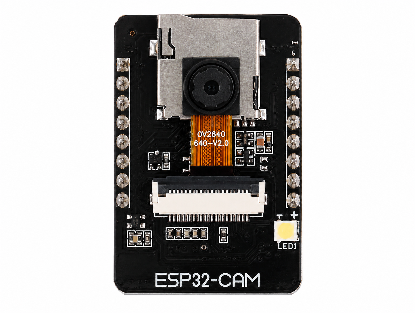
The ESP32-CAM is a low-cost development board manufactured by AI-Thinker (Part ID: ESP32-CAM-AI-THINKER) that combines the powerful ESP32 microcontroller with integrated Wi-Fi and Bluetooth capabilities, along with a camera module. This compact and versatile board is ideal for IoT projects requiring video streaming, image capture, and wireless communication.
Explore Projects Built with ESP32-CAM


Explore Projects Built with ESP32-CAM
Common Applications
- Wireless video surveillance systems
- Smart home devices (e.g., doorbell cameras, baby monitors)
- IoT-enabled image recognition and processing
- Remote-controlled robots with live video feed
- Environmental monitoring with visual data capture
Technical Specifications
Key Technical Details
| Parameter | Specification |
|---|---|
| Microcontroller | ESP32-D0WD |
| Wireless Connectivity | Wi-Fi 802.11 b/g/n, Bluetooth 4.2 (Classic and BLE) |
| Camera Module | OV2640 (2MP resolution) |
| Flash Memory | 4 MB SPI Flash |
| RAM | 520 KB SRAM + 4 MB PSRAM |
| Operating Voltage | 3.3V |
| Input Voltage Range | 5V (via external power supply or USB-to-TTL adapter) |
| GPIO Pins | 9 GPIO pins available for user applications |
| Interfaces | UART, SPI, I2C, PWM, ADC |
| Power Consumption | Deep Sleep: ~6mA, Active Mode: ~160mA |
| Dimensions | 27mm x 40.5mm |
Pin Configuration and Descriptions
The ESP32-CAM has a total of 16 pins. Below is the pinout and description:
| Pin Name | Pin Number | Description |
|---|---|---|
| GND | 1 | Ground connection |
| 3.3V | 2 | 3.3V power output |
| 5V | 3 | 5V power input |
| GPIO1 | 4 | UART TX (used for programming/debugging) |
| GPIO3 | 5 | UART RX (used for programming/debugging) |
| GPIO0 | 6 | Boot mode selection (connect to GND for flashing firmware) |
| GPIO2 | 7 | General-purpose I/O pin |
| GPIO4 | 8 | General-purpose I/O pin |
| GPIO12 | 9 | General-purpose I/O pin |
| GPIO13 | 10 | General-purpose I/O pin |
| GPIO14 | 11 | General-purpose I/O pin |
| GPIO15 | 12 | General-purpose I/O pin |
| GPIO16 | 13 | General-purpose I/O pin |
| GPIO33 | 14 | General-purpose I/O pin |
| RESET | 15 | Reset pin |
| GND | 16 | Ground connection |
Note: The ESP32-CAM does not have a built-in USB interface. A USB-to-TTL adapter is required for programming.
Usage Instructions
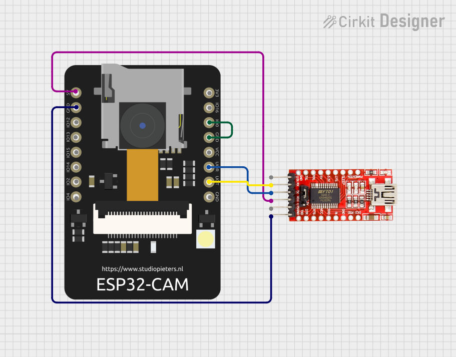
How to Use the ESP32-CAM in a Circuit
Powering the Board:
- Connect the 5V pin to a 5V power source (e.g., USB-to-TTL adapter or external power supply).
- Ensure the GND pin is connected to the ground of the power source.
Programming the Board:
- Use a USB-to-TTL adapter to connect the ESP32-CAM to your computer.
- Connect the adapter's TX pin to GPIO3 (RX) and RX pin to GPIO1 (TX).
- Connect GPIO0 to GND to enable flashing mode.
- Use the Arduino IDE or ESP-IDF to upload your code.
Connecting the Camera:
- The OV2640 camera module is pre-installed on the board. Ensure it is securely connected to the camera connector.
Using GPIO Pins:
- The GPIO pins can be used for interfacing with sensors, actuators, or other peripherals.
- Be cautious of the 3.3V logic level when connecting external devices.
Important Considerations
- Power Supply: Ensure a stable 5V power supply to avoid unexpected resets or malfunctions.
- Heat Management: The ESP32-CAM can get warm during operation. Consider adding a heatsink for prolonged use.
- Antenna Selection: The board has an onboard PCB antenna and a U.FL connector for an external antenna. Use the onboard jumper to select the desired antenna.
Example Code for Arduino UNO Integration
Below is an example of how to use the ESP32-CAM for video streaming. This code sets up the ESP32-CAM as a web server to stream video.
#include <WiFi.h>
#include <esp_camera.h>

// Replace with your Wi-Fi credentials
const char* ssid = "Your_SSID";
const char* password = "Your_PASSWORD";

// Camera configuration
#define PWDN_GPIO_NUM    -1
#define RESET_GPIO_NUM   -1
#define XCLK_GPIO_NUM     0
#define SIOD_GPIO_NUM    26
#define SIOC_GPIO_NUM    27
#define Y9_GPIO_NUM      35
#define Y8_GPIO_NUM      34
#define Y7_GPIO_NUM      39
#define Y6_GPIO_NUM      36
#define Y5_GPIO_NUM      21
#define Y4_GPIO_NUM      19
#define Y3_GPIO_NUM      18
#define Y2_GPIO_NUM       5
#define VSYNC_GPIO_NUM   25
#define HREF_GPIO_NUM    23
#define PCLK_GPIO_NUM    22

void startCameraServer();

void setup() {
  Serial.begin(115200);
  WiFi.begin(ssid, password);

  // Wait for Wi-Fi connection
  while (WiFi.status() != WL_CONNECTED) {
    delay(500);
    Serial.print(".");
  }
  Serial.println("\nWi-Fi connected");

  // Configure camera
  camera_config_t config;
  config.ledc_channel = LEDC_CHANNEL_0;
  config.ledc_timer = LEDC_TIMER_0;
  config.pin_d0 = Y2_GPIO_NUM;
  config.pin_d1 = Y3_GPIO_NUM;
  config.pin_d2 = Y4_GPIO_NUM;
  config.pin_d3 = Y5_GPIO_NUM;
  config.pin_d4 = Y6_GPIO_NUM;
  config.pin_d5 = Y7_GPIO_NUM;
  config.pin_d6 = Y8_GPIO_NUM;
  config.pin_d7 = Y9_GPIO_NUM;
  config.pin_xclk = XCLK_GPIO_NUM;
  config.pin_pclk = PCLK_GPIO_NUM;
  config.pin_vsync = VSYNC_GPIO_NUM;
  config.pin_href = HREF_GPIO_NUM;
  config.pin_sscb_sda = SIOD_GPIO_NUM;
  config.pin_sscb_scl = SIOC_GPIO_NUM;
  config.pin_pwdn = PWDN_GPIO_NUM;
  config.pin_reset = RESET_GPIO_NUM;
  config.xclk_freq_hz = 20000000;
  config.pixel_format = PIXFORMAT_JPEG;

  // Initialize camera
  if (esp_camera_init(&config) != ESP_OK) {
    Serial.println("Camera initialization failed");
    return;
  }

  // Start camera server
  startCameraServer();
  Serial.println("Camera ready! Stream at: http://" + WiFi.localIP().toString());
}

void loop() {
  // Main loop does nothing; camera server handles requests
}
Troubleshooting and FAQs
Common Issues
Camera Initialization Failed:
- Ensure the camera module is securely connected to the board.
- Verify the camera configuration in the code matches the hardware.
Wi-Fi Connection Issues:
- Double-check the SSID and password in your code.
- Ensure the ESP32-CAM is within range of your Wi-Fi router.
Board Not Detected During Programming:
- Confirm the USB-to-TTL adapter is properly connected.
- Ensure GPIO0 is connected to GND during flashing.
Overheating:
- Use a heatsink or ensure proper ventilation if the board gets too hot.
Tips for Troubleshooting
- Use the Serial Monitor to debug issues during programming or runtime.
- Check the power supply voltage and current to ensure stability.
- If the board fails to boot, press the RESET button after powering it on.
By following this documentation, you can effectively use the ESP32-CAM for your IoT and video streaming projects.