Cirkit Designer
Your all-in-one circuit design IDE
Home /
Component Documentation
How to Use Active buzzer: Examples, Pinouts, and Specs
Introduction
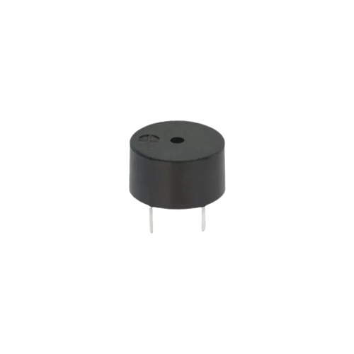
An active buzzer is a sound-producing device that generates sound when an electrical signal is applied. Unlike a passive buzzer, an active buzzer contains a built-in oscillator, which simplifies its operation as it does not require an external signal generator. It operates on DC voltage and is widely used in circuits for alarms, notifications, and alerts.
Explore Projects Built with Active buzzer
Voice-Controlled Buzzer System with VC-02 Module

This circuit features a VC-02 voice recognition module connected to a buzzer and powered by a 5V battery. The VC-02 module is programmed to listen for specific voice commands and, upon recognizing the command 'can you make a sound', it activates the buzzer for one second. The circuit is designed for voice-activated sound generation, with the VC-02 module handling voice recognition and serial communication, and the buzzer providing audible feedback.
Battery-Powered Buzzer Circuit
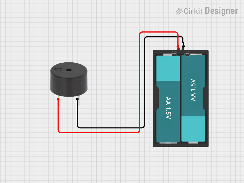
This circuit consists of a simple buzzer connected to a 3V battery source. The positive terminal of the battery is connected to the buzzer's power input, and the negative terminal is connected to the buzzer's ground. The circuit is designed to power the buzzer continuously, producing a constant sound or tone as long as the battery provides sufficient voltage.
Wi-Fi Controlled Buzzer with Wemos D1 Mini
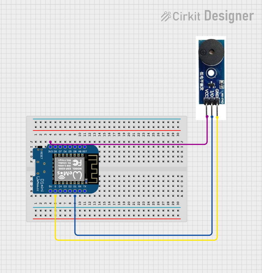
This circuit consists of a Wemos D1 Mini microcontroller connected to an active buzzer module. The Wemos D1 Mini provides power to the buzzer and controls it through its D1 pin, allowing for programmable sound output.
Arduino UNO Sound-Activated Buzzer System
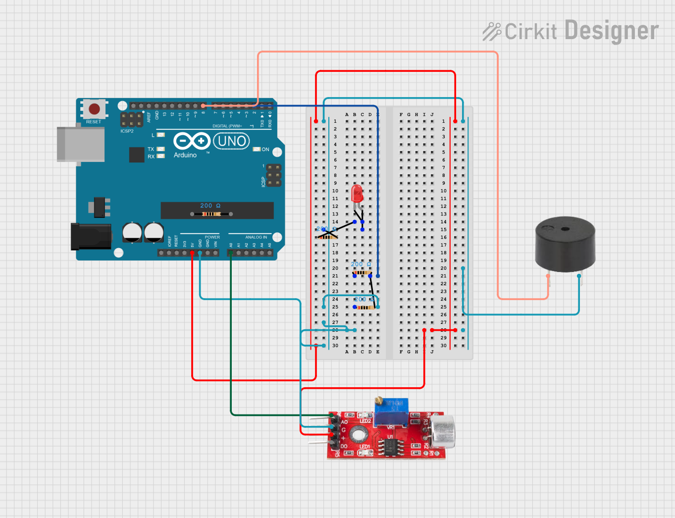
This circuit includes an Arduino UNO microcontroller interfaced with a sound sensor and a buzzer. The sound sensor's analog output is connected to the Arduino's A0 pin, and the buzzer is connected to digital pin D8. The Arduino is programmed to activate the buzzer when a certain sound threshold is detected by the sound sensor; however, the LED in the circuit is not utilized by the current program.
Explore Projects Built with Active buzzer
Voice-Controlled Buzzer System with VC-02 Module
This circuit features a VC-02 voice recognition module connected to a buzzer and powered by a 5V battery. The VC-02 module is programmed to listen for specific voice commands and, upon recognizing the command 'can you make a sound', it activates the buzzer for one second. The circuit is designed for voice-activated sound generation, with the VC-02 module handling voice recognition and serial communication, and the buzzer providing audible feedback.
Battery-Powered Buzzer Circuit
This circuit consists of a simple buzzer connected to a 3V battery source. The positive terminal of the battery is connected to the buzzer's power input, and the negative terminal is connected to the buzzer's ground. The circuit is designed to power the buzzer continuously, producing a constant sound or tone as long as the battery provides sufficient voltage.
Wi-Fi Controlled Buzzer with Wemos D1 Mini
This circuit consists of a Wemos D1 Mini microcontroller connected to an active buzzer module. The Wemos D1 Mini provides power to the buzzer and controls it through its D1 pin, allowing for programmable sound output.
Arduino UNO Sound-Activated Buzzer System
This circuit includes an Arduino UNO microcontroller interfaced with a sound sensor and a buzzer. The sound sensor's analog output is connected to the Arduino's A0 pin, and the buzzer is connected to digital pin D8. The Arduino is programmed to activate the buzzer when a certain sound threshold is detected by the sound sensor; however, the LED in the circuit is not utilized by the current program.
Common Applications
- Alarm systems (e.g., burglar alarms, fire alarms)
- Timers and reminders
- Notification systems in appliances
- Toys and educational projects
- Arduino-based projects for sound alerts
Technical Specifications
Key Technical Details
| Parameter | Value |
|---|---|
| Operating Voltage | 3V to 12V DC |
| Rated Voltage | 5V DC |
| Current Consumption | ≤ 30mA |
| Sound Output Level | 85 dB at 10 cm (typical) |
| Frequency | 2 kHz to 4 kHz (built-in) |
| Operating Temperature | -20°C to +70°C |
| Dimensions | Varies (e.g., 12mm diameter) |
Pin Configuration and Descriptions
| Pin Name | Description |
|---|---|
| Positive (+) | Connect to the positive terminal of the power supply or microcontroller output pin. |
| Negative (-) | Connect to the ground (GND) of the circuit. |
Usage Instructions
How to Use the Active Buzzer in a Circuit
- Power Connection: Connect the positive pin of the buzzer to the power supply or the output pin of a microcontroller (e.g., Arduino). Connect the negative pin to the ground (GND).
- Voltage Supply: Ensure the supply voltage is within the operating range (typically 3V to 12V). A 5V supply is commonly used in microcontroller projects.
- Control: The active buzzer can be turned on or off by applying a HIGH or LOW signal to the positive pin. No additional circuitry is required since the oscillator is built-in.
Important Considerations
- Polarity: Ensure correct polarity when connecting the buzzer. Reversing the connections may damage the component.
- Power Supply: Avoid exceeding the maximum voltage rating to prevent damage.
- Mounting: Secure the buzzer in place to avoid vibrations affecting its performance.
- Noise Level: Place the buzzer away from sensitive components to minimize interference.
Example: Using an Active Buzzer with Arduino UNO
Below is an example of how to connect and control an active buzzer using an Arduino UNO:
Circuit Diagram
- Connect the positive pin of the buzzer to Arduino digital pin 8.
- Connect the negative pin of the buzzer to the Arduino GND.
Code Example
// Active Buzzer Example with Arduino UNO
// This code turns the buzzer on for 1 second and off for 1 second repeatedly.

#define BUZZER_PIN 8  // Define the pin connected to the buzzer

void setup() {
  pinMode(BUZZER_PIN, OUTPUT); // Set the buzzer pin as an output
}

void loop() {
  digitalWrite(BUZZER_PIN, HIGH); // Turn the buzzer on
  delay(1000);                   // Wait for 1 second
  digitalWrite(BUZZER_PIN, LOW);  // Turn the buzzer off
  delay(1000);                   // Wait for 1 second
}
Best Practices
- Use a current-limiting resistor if the buzzer draws more current than the microcontroller pin can supply.
- Test the buzzer in a breadboard setup before soldering it into a permanent circuit.
Troubleshooting and FAQs
Common Issues and Solutions
| Issue | Possible Cause | Solution |
|---|---|---|
| No sound from the buzzer | Incorrect polarity connection | Verify and correct the polarity. |
| Low or distorted sound | Insufficient supply voltage | Ensure the voltage is within the range (e.g., 5V). |
| Buzzer not turning off | Microcontroller pin not set to LOW | Check the control signal in the code. |
| Buzzer overheating | Exceeding voltage or current rating | Use a proper power supply and check ratings. |
FAQs
Can I use an active buzzer with a 3.3V microcontroller?
- Yes, as long as the buzzer's operating voltage includes 3.3V. Check the datasheet for compatibility.
What is the difference between an active and a passive buzzer?
- An active buzzer has a built-in oscillator and only requires a DC voltage to produce sound. A passive buzzer requires an external signal (e.g., PWM) to generate sound.
Can I control the sound frequency of an active buzzer?
- No, the frequency is fixed by the built-in oscillator. For variable frequencies, use a passive buzzer.
Why is my buzzer making a faint clicking noise instead of a tone?
- This could be due to insufficient voltage or a damaged oscillator. Verify the power supply and replace the buzzer if necessary.