Cirkit Designer
Your all-in-one circuit design IDE
Home /
Component Documentation
How to Use LED: Two Pin (green): Examples, Pinouts, and Specs
Introduction
A green LED (Light-Emitting Diode) with two pins is a semiconductor light source that emits green light when an electric current flows through it. LEDs are widely used in various applications due to their low power consumption, long service life, and compact size. Green LEDs, in particular, are often used in electronics to indicate power status, signal messages, or as part of user interfaces.
Explore Projects Built with LED: Two Pin (green)
Pushbutton-Controlled Dual-Color LED Circuit with TA6568

This is a pushbutton-controlled LED circuit with a TA6568 chip that likely drives two LEDs (red and green). Each LED is connected to a pushbutton through the TA6568, allowing the user to toggle the state of the LEDs. The circuit is powered by a 3V battery and includes a JST connector for external interfacing.
LED Array with Inductive Power Transfer

The circuit consists of multiple red two-pin LEDs connected in parallel, with all cathodes tied together and all anodes tied together. A copper coil is also connected in parallel with the LEDs. There is no control circuitry or power regulation components indicated, and no embedded code provided, suggesting this is a simple illumination circuit possibly intended for inductive power transfer given the presence of the copper coil.
Battery-Powered LED Indicator with Directional Switch
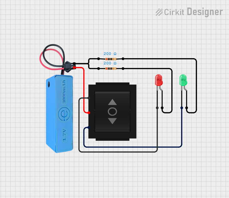
This circuit uses a directional switch to control two LEDs (one red and one green). Depending on the switch position, either the red or green LED will light up, with each LED connected in series with a 200-ohm resistor to limit the current, powered by a 3.7V source.
Battery-Powered LED Array with Rocker Switch Control

This circuit consists of four green LEDs connected in parallel, powered by a 9V battery. A rocker switch is used to control the power to the LEDs, allowing them to be turned on or off simultaneously.
Explore Projects Built with LED: Two Pin (green)
Pushbutton-Controlled Dual-Color LED Circuit with TA6568
This is a pushbutton-controlled LED circuit with a TA6568 chip that likely drives two LEDs (red and green). Each LED is connected to a pushbutton through the TA6568, allowing the user to toggle the state of the LEDs. The circuit is powered by a 3V battery and includes a JST connector for external interfacing.
LED Array with Inductive Power Transfer
The circuit consists of multiple red two-pin LEDs connected in parallel, with all cathodes tied together and all anodes tied together. A copper coil is also connected in parallel with the LEDs. There is no control circuitry or power regulation components indicated, and no embedded code provided, suggesting this is a simple illumination circuit possibly intended for inductive power transfer given the presence of the copper coil.
Battery-Powered LED Indicator with Directional Switch
This circuit uses a directional switch to control two LEDs (one red and one green). Depending on the switch position, either the red or green LED will light up, with each LED connected in series with a 200-ohm resistor to limit the current, powered by a 3.7V source.
Battery-Powered LED Array with Rocker Switch Control
This circuit consists of four green LEDs connected in parallel, powered by a 9V battery. A rocker switch is used to control the power to the LEDs, allowing them to be turned on or off simultaneously.
Common Applications and Use Cases
- Indicator lights on electronic devices
- Backlighting for LCD displays
- Traffic signals and signage
- Decorative and architectural lighting
- Hobbyist projects, including Arduino-based circuits
Technical Specifications
Key Technical Details
- Forward Voltage (Vf): Typically 2.0V to 3.4V
- Forward Current (If): Recommended 20mA (max. current without risking damage)
- Luminous Intensity: Varies with current and manufacturer, typically around 20 mcd (millicandela)
- Viewing Angle: Typically between 20° and 30°
- Peak Wavelength: Approximately 520nm to 570nm (green spectrum)
Pin Configuration and Descriptions
| Pin Number | Name | Description |
|---|---|---|
| 1 | Anode (+) | Connects to the positive supply voltage |
| 2 | Cathode (-) | Connects to the ground (0V) |
Usage Instructions
How to Use the Component in a Circuit
- Identify the Pins: The longer pin is usually the anode (positive), and the shorter pin is the cathode (negative).
- Current Limiting Resistor: Always use a current-limiting resistor in series with the LED to prevent it from drawing excessive current. The value of the resistor can be calculated using Ohm's law:
R = (V_supply - Vf) / If. - Polarity: Connect the anode to the positive voltage supply and the cathode to the negative side (ground) through the current-limiting resistor.
- Power Supply: Ensure that the power supply voltage is appropriate for the LED. Exceeding the maximum forward voltage can damage the LED.
Important Considerations and Best Practices
- Do not exceed the maximum forward current rating.
- Use a resistor with an appropriate power rating to avoid overheating.
- Consider using a PWM (Pulse Width Modulation) signal to control the brightness of the LED.
- When using multiple LEDs, connect each with its own current-limiting resistor to ensure even brightness.
Troubleshooting and FAQs
Common Issues Users Might Face
- LED Not Lighting Up: Check the polarity of the connections and ensure the power supply is functioning.
- Dim LED: Confirm that the current-limiting resistor value is correct and that the power supply voltage is adequate.
- LED Burnt Out: The LED may have been subjected to excessive current or voltage. Replace the LED and verify the circuit design.
Solutions and Tips for Troubleshooting
- Use a multimeter to check for continuity and proper voltage levels in the circuit.
- Ensure that solder joints are secure and free of shorts.
- If using with a microcontroller like Arduino, verify that the output pin is configured correctly in the code.
Example Code for Arduino UNO
// Define the LED pin
const int ledPin = 13; // Most Arduino UNOs have an onboard LED on pin 13

void setup() {
  // Set the LED pin as an output
  pinMode(ledPin, OUTPUT);
}

void loop() {
  // Turn the LED on (HIGH is the voltage level)
  digitalWrite(ledPin, HIGH);
  // Wait for a second
  delay(1000);
  // Turn the LED off by making the voltage LOW
  digitalWrite(ledPin, LOW);
   // Wait for a second
  delay(1000);
}
Note: The onboard LED on the Arduino UNO is connected with a built-in resistor, so you do not need to add an external current-limiting resistor for pin 13. However, for external LEDs, always include a resistor in the circuit.