How to Use HW-040 Rotary Encoder: Examples, Pinouts, and Specs
Introduction
The HW-040 Rotary Encoder is an electro-mechanical component that translates the angular position or motion of a shaft into analog or digital output signals. This encoder is particularly useful in applications where precise rotational feedback is required, such as in user input devices (e.g., volume controls, menu selection), robotics, industrial controls, and position monitoring.
Explore Projects Built with HW-040 Rotary Encoder
Explore Projects Built with HW-040 Rotary Encoder
Common Applications and Use Cases
- Volume control in audio equipment
- User interface controls in systems with limited user input options
- Position sensing in robotics and automation
- Digital potentiometer replacement
- Rotary dial for menu navigation in electronic devices
Technical Specifications
Key Technical Details
- Operating Voltage: 5V
- Pulse/Step Count: 20 per revolution
- Detent Count: 20 detents per revolution
- Shaft Diameter: 6mm
- Output: Quadrature encoded signal
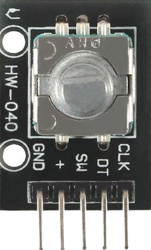
Pin Configuration and Descriptions
| Pin Number | Name | Description |
|---|---|---|
| 1 | GND | Ground connection |
| 2 | + | Power supply (5V) |
| 3 | SW | Push-button switch output |
| 4 | DT | Data output |
| 5 | CLK | Clock output |
Usage Instructions
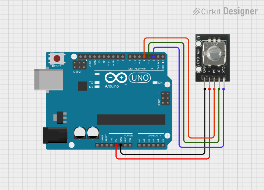
How to Use the Component in a Circuit
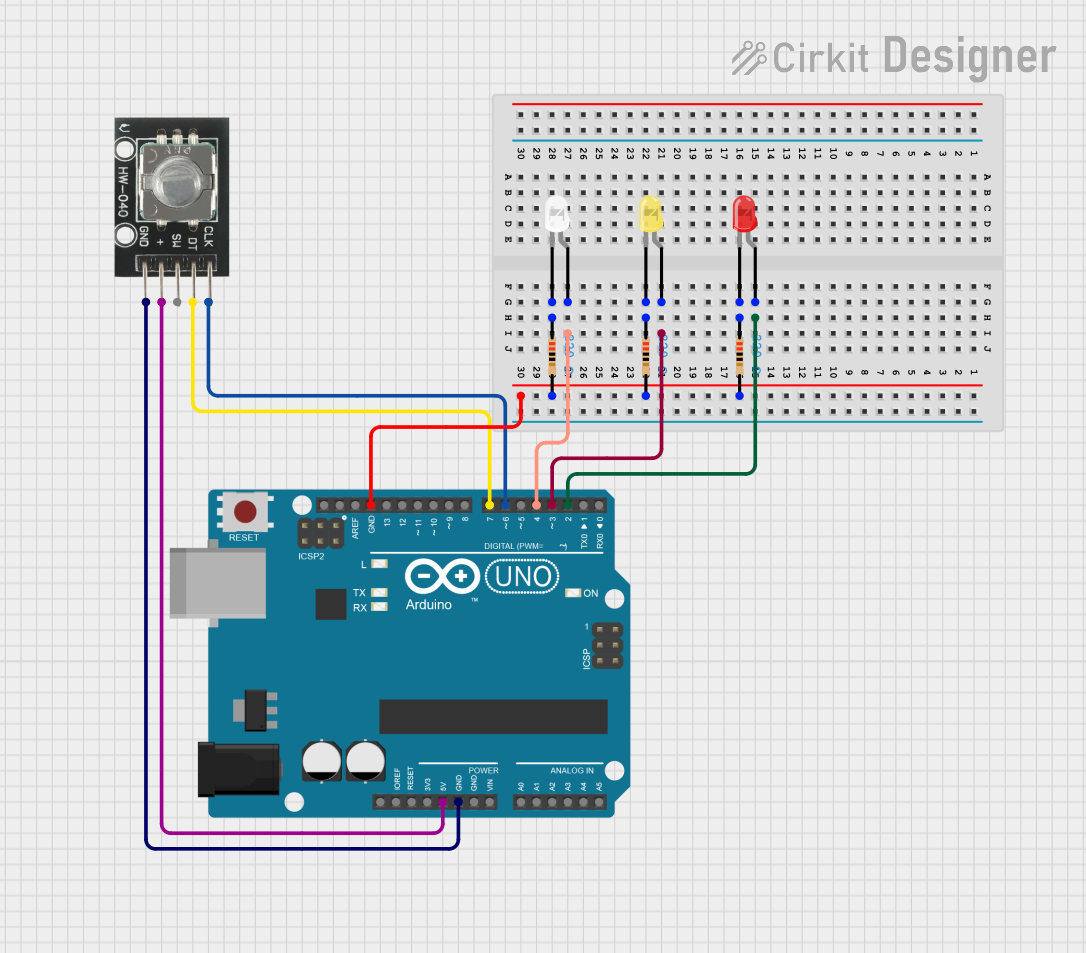
- Connect the GND pin to the ground of your circuit.
- Connect the + pin to a 5V power supply.
- Connect the DT and CLK pins to two digital input pins on your microcontroller.
- (Optional) Connect the SW pin to another digital input pin if you wish to use the integrated push-button feature.
Important Considerations and Best Practices
- Use pull-up resistors on the DT and CLK lines to ensure reliable signal levels.
- Debounce the SW pin either in hardware or software to avoid false triggering from mechanical switch noise.
- Monitor the CLK and DT pins for changes to determine the direction of rotation.
- Implement an interrupt service routine (ISR) for handling the rotary encoder signals to improve response time and accuracy.
Example Code for Arduino UNO
// Define the connections to the Arduino
const int pinCLK = 2; // Connected to CLK on the rotary encoder
const int pinDT = 3;  // Connected to DT on the rotary encoder
const int pinSW = 4;  // Connected to SW on the rotary encoder

// Variables to hold the current and last encoder position
volatile int encoderPos = 0;
int lastEncoderPos = 0;

// Variables to keep track of the state of the pins
int lastCLK;
int currentCLK;

// Setup function runs once at the start of the program
void setup() {
  pinMode(pinCLK, INPUT_PULLUP);
  pinMode(pinDT, INPUT_PULLUP);
  pinMode(pinSW, INPUT_PULLUP);

  // Attach an interrupt to the CLK pin
  attachInterrupt(digitalPinToInterrupt(pinCLK), readEncoder, CHANGE);

  // Initialize the serial communication
  Serial.begin(9600);

  // Read the initial state of CLK
  lastCLK = digitalRead(pinCLK);
}

// Main program loop
void loop() {
  // Check if the encoder has moved
  if (encoderPos != lastEncoderPos) {
    Serial.print("Position: ");
    Serial.println(encoderPos);
    lastEncoderPos = encoderPos;
  }

  // Check if the button is pressed
  if (digitalRead(pinSW) == LOW) {
    // Reset the encoder position to 0
    encoderPos = 0;
    Serial.println("Reset to 0");
    // Wait for the button to be released
    while (digitalRead(pinSW) == LOW) delay(10);
  }
}

// Interrupt service routine for reading the encoder
void readEncoder() {
  currentCLK = digitalRead(pinCLK);
  // If the current state of CLK is different from the last state
  // then a pulse occurred
  if (currentCLK != lastCLK) {
    // If the DT state is different from the CLK state
    // then the encoder is rotating clockwise
    if (digitalRead(pinDT) != currentCLK) {
      encoderPos++;
    } else {
      // Otherwise, it's rotating counterclockwise
      encoderPos--;
    }
  }
  // Update lastCLK with the current state for the next pulse detection
  lastCLK = currentCLK;
}
Troubleshooting and FAQs
Common Issues Users Might Face
- Erratic Signals: If the encoder outputs erratic signals, ensure that the pull-up resistors are properly connected and that the encoder is not subject to mechanical vibrations.
- No Response: Check the wiring and ensure that the power supply is at the correct voltage level.
- Inaccurate Positioning: Implement software debouncing or use hardware filters to stabilize the signal.
Solutions and Tips for Troubleshooting
- Debouncing: Implement a software debounce algorithm or use a hardware debounce circuit to filter out noise from the switch.
- Signal Filtering: Add a low-pass filter to the output signals if there is a lot of electrical noise in the environment.
- Check Connections: Ensure that all connections are secure and that there are no cold solder joints or loose wires.
FAQs
Q: Can the HW-040 Rotary Encoder be used with a 3.3V system? A: Yes, but the output signal levels will be lower, which may require level shifting for some 5V microcontrollers.
Q: How can I increase the resolution of the encoder? A: The HW-040 has a fixed resolution of 20 pulses per revolution. To increase the effective resolution, you can use gear reduction or employ software algorithms to interpolate between steps.
Q: Is it possible to use the HW-040 Rotary Encoder without an interrupt? A: Yes, but using interrupts is recommended for better performance, especially at higher rotation speeds. Without interrupts, you may miss pulses if the encoder is turned quickly.