How to Use adxl 355: Examples, Pinouts, and Specs
Introduction
The ADXL355 is a high precision, low-power, 3-axis MEMS accelerometer designed by Analog Devices Inc. It is capable of measuring acceleration with a high resolution of up to 3.9µg/LSB and low noise performance, making it suitable for a wide range of applications including industrial monitoring, medical devices, platform stabilization, and inertial navigation.
Explore Projects Built with adxl 355
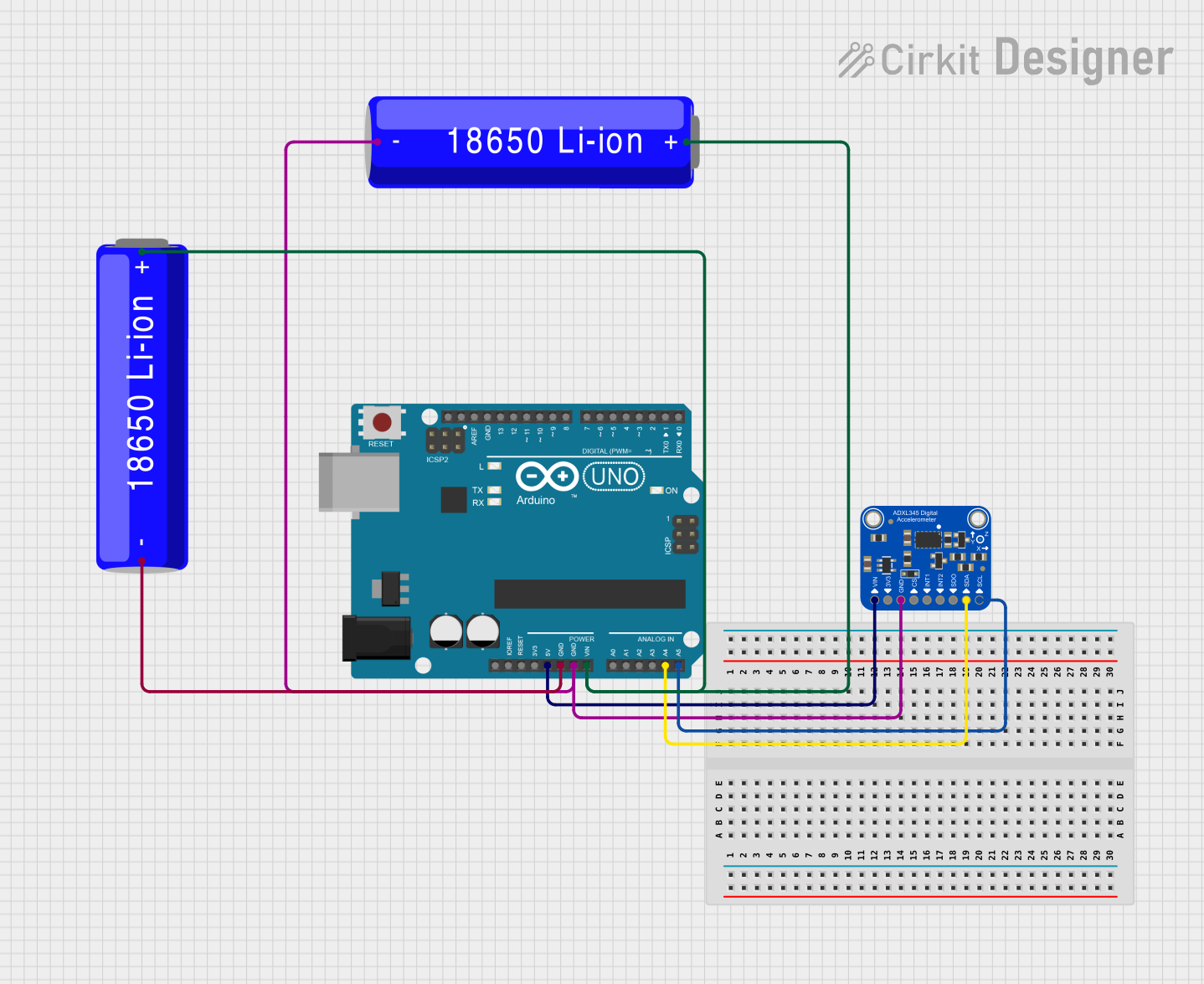
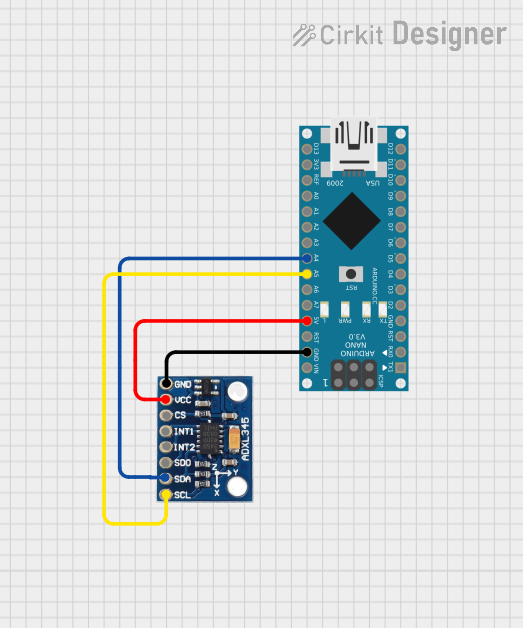

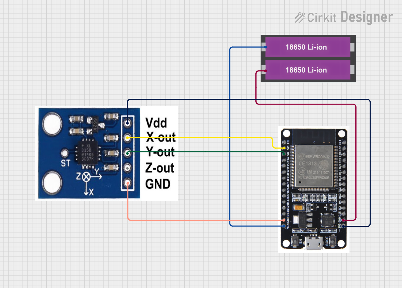
Explore Projects Built with adxl 355
Common Applications and Use Cases
- Vibration analysis and monitoring
- Tilt sensing in robotics and automotive systems
- Motion detection in security systems
- Structural health monitoring
- Inertial measurement units (IMUs) for navigation
Technical Specifications
Key Technical Details
- Power Supply Voltage (VDD_IO): 1.8V to 3.3V
- Measurement Range: ±2g, ±4g, ±8g (selectable)
- Resolution: Up to 3.9µg/LSB
- Output Data Rate (ODR): 4Hz to 4000Hz (selectable)
- Interface: SPI (3- or 4-wire) or I2C
- Temperature Range: -40°C to +125°C
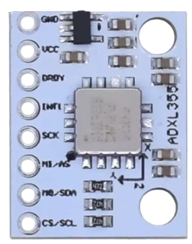
Pin Configuration and Descriptions
| Pin Number | Pin Name | Description |
|---|---|---|
| 1 | VDD | Power supply voltage (2.25V to 3.6V) |
| 2 | GND | Ground reference for the power supply |
| 3 | CS | Chip select for SPI interface (active low) |
| 4 | INT1 | Interrupt output 1 |
| 5 | INT2 | Interrupt output 2 |
| 6 | SDO/ALT ADDRESS | SPI serial data output / I2C alternate address selection |
| 7 | SDA/SDI | I2C data line / SPI serial data input |
| 8 | SCL/SCLK | I2C clock line / SPI serial clock input |
| 9 | DRDY | Data ready indicator output |
| 10 | TEMP | Temperature sensor output (optional use) |
| 11 | RSV | Reserved. Connect to GND. |
| 12 | RSV | Reserved. Connect to GND. |
Usage Instructions
How to Use the Component in a Circuit
- Power Supply: Connect VDD to a 2.25V to 3.6V power source and GND to the system ground.
- Communication Interface: Choose between SPI or I2C for communication with a microcontroller, such as an Arduino UNO.
- Data Ready (DRDY): Connect DRDY to an interrupt pin on the microcontroller to detect when new data is available.
- Chip Select (CS): For SPI, connect CS to a digital pin on the microcontroller and control it accordingly.
- Interrupt Outputs (INT1, INT2): Optionally connect these to microcontroller pins if using the interrupt features.
Important Considerations and Best Practices
- Ensure that the power supply is stable and within the specified voltage range.
- Use proper decoupling capacitors close to the power supply pins to minimize noise.
- Avoid physical stress and overheating during soldering and handling.
- Calibrate the accelerometer after installation to account for any zero-g offset.
Example Code for Arduino UNO
#include <Wire.h> // Include the I2C library (required for the ADXL355)

// ADXL355 I2C address (check datasheet for your device's address)
#define ADXL355_ADDRESS 0x1D

// ADXL355 registers
#define DEVID_AD 0x00
// Add additional register definitions here

void setup() {
  Wire.begin(); // Initialize I2C
  Serial.begin(9600); // Start serial communication at 9600 baud

  // Check device ID
  if (readRegister(DEVID_AD) == 0xAD) {
    Serial.println("ADXL355 found!");
  } else {
    Serial.println("Device not found. Check connections.");
  }

  // Initialize the ADXL355 here
  // Configure measurement range, output data rate, etc.
}

void loop() {
  // Read acceleration data
  // Convert raw data to g's and output the results
  // Implement data reading and conversion here
}

// Function to read a register from the ADXL355
byte readRegister(byte reg) {
  Wire.beginTransmission(ADXL355_ADDRESS);
  Wire.write(reg);
  Wire.endTransmission();
  Wire.requestFrom(ADXL355_ADDRESS, 1);
  return Wire.read();
}

// Add additional functions for writing to registers, reading multiple bytes, etc.
Troubleshooting and FAQs
Common Issues Users Might Face
- No Data Output: Ensure that the power supply is within range and all connections are secure. Check that the correct I2C address or SPI settings are being used.
- Inaccurate Readings: Calibrate the sensor for zero-g offset and ensure that the sensor is not subjected to mechanical stress or thermal variation beyond specified limits.
- Communication Errors: Verify the integrity of the I2C or SPI lines, check for proper pull-up resistors on I2C lines, and ensure that there is no bus contention.
Solutions and Tips for Troubleshooting
- Power Supply Issues: Use a multimeter to verify the voltage at the VDD pin.
- Signal Integrity: Use an oscilloscope to check the SDA, SCL (I2C) or SDI, SDO, SCLK (SPI) lines for proper signaling.
- Sensor Calibration: Follow the calibration procedure outlined in the ADXL355 datasheet to correct for any offset errors.
FAQs
Q: Can the ADXL355 be used in battery-powered applications? A: Yes, the ADXL355 is designed for low-power operation, making it suitable for battery-powered devices.
Q: How do I select the measurement range? A: The measurement range can be set by writing to the appropriate register. Refer to the datasheet for the specific register settings.
Q: What is the maximum sampling rate of the ADXL355? A: The ADXL355 can sample up to 4000Hz, but the actual maximum rate depends on the selected output data rate (ODR) setting.
This documentation provides a comprehensive guide to the ADXL355 accelerometer, enabling users to integrate it into their projects effectively. For further details and advanced features, refer to the official datasheet provided by Analog Devices Inc.