How to Use Microstep Diver DM542: Examples, Pinouts, and Specs
Introduction
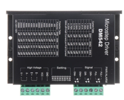
The DM542 is a digital stepper motor driver designed to provide precise control of stepper motors with advanced microstepping capabilities. It supports a wide range of input voltages (20-50V DC) and offers adjustable current settings, making it versatile for various applications. The DM542 is commonly used in robotics, CNC machines, 3D printers, and other automation systems where precise motor control is essential. Its robust design ensures reliable performance, even in demanding environments.
Explore Projects Built with Microstep Diver DM542

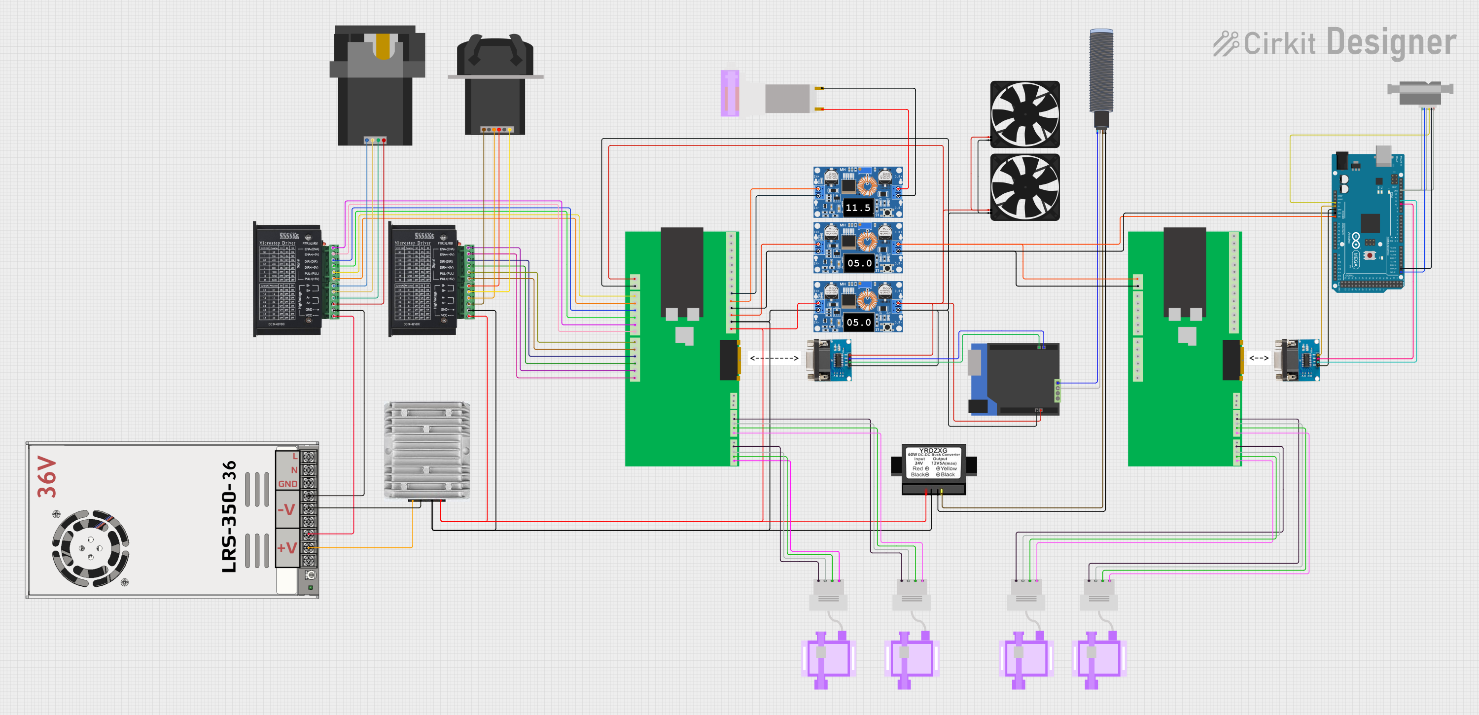

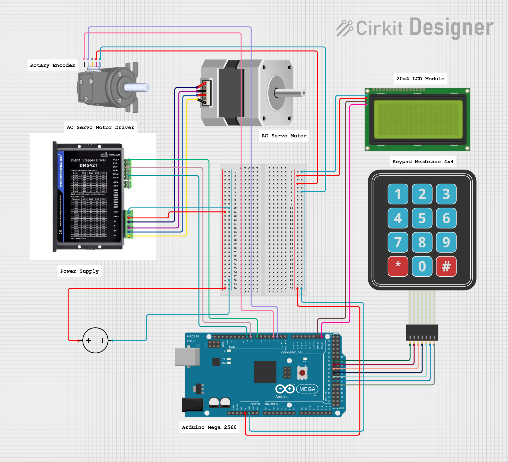
Explore Projects Built with Microstep Diver DM542
Technical Specifications
The DM542 offers a range of features and specifications that make it a reliable choice for stepper motor control. Below are the key technical details:
General Specifications
| Parameter | Value |
|---|---|
| Input Voltage Range | 20-50V DC |
| Output Current Range | 1.0A - 4.2A (adjustable) |
| Microstepping Settings | 1, 2, 4, 8, 16, 32, 64, 128 |
| Control Signal Voltage | 5V (compatible with TTL logic) |
| Step Frequency Range | 0-200 kHz |
| Operating Temperature | -10°C to +45°C |
| Storage Temperature | -40°C to +70°C |
| Humidity | 40-90% (non-condensing) |
Pin Configuration and Descriptions
The DM542 has two main connectors: one for motor and power connections and another for control signals. Below is the pin configuration:
Motor and Power Connector
| Pin Name | Description |
|---|---|
| A+ | Positive terminal for motor coil A |
| A- | Negative terminal for motor coil A |
| B+ | Positive terminal for motor coil B |
| B- | Negative terminal for motor coil B |
| VCC | Power supply positive (20-50V DC) |
| GND | Power supply ground |
Control Signal Connector
| Pin Name | Description |
|---|---|
| PUL+ | Pulse signal input (positive) |
| PUL- | Pulse signal input (negative) |
| DIR+ | Direction signal input (positive) |
| DIR- | Direction signal input (negative) |
| ENA+ | Enable signal input (positive, optional) |
| ENA- | Enable signal input (negative, optional) |
Usage Instructions
How to Use the DM542 in a Circuit
- Power Supply: Connect a DC power supply (20-50V) to the VCC and GND terminals. Ensure the power supply can provide sufficient current for the motor.
- Motor Connection: Connect the stepper motor coils to the A+, A-, B+, and B- terminals. Refer to the motor datasheet to identify the correct coil pairs.
- Control Signals: Connect the PUL+, PUL-, DIR+, DIR-, ENA+, and ENA- pins to a microcontroller or control board (e.g., Arduino UNO). Use appropriate pull-up or pull-down resistors if required.
- Microstepping and Current Settings: Use the DIP switches on the DM542 to configure the microstepping resolution and output current. Refer to the DM542 datasheet for DIP switch settings.
- Testing: Power on the system and send pulse and direction signals from the controller to test motor movement.
Important Considerations and Best Practices
- Current Settings: Set the output current to match the stepper motor's rated current to avoid overheating or underpowering the motor.
- Microstepping: Choose a microstepping setting that balances precision and torque for your application.
- Signal Quality: Ensure clean and noise-free control signals to avoid erratic motor behavior.
- Cooling: Provide adequate ventilation or a heatsink for the DM542 if it operates in a high-temperature environment.
Example: Connecting DM542 to Arduino UNO
Below is an example Arduino code to control a stepper motor using the DM542:
// Define control pins
const int pulsePin = 3; // Pin for PUL+ (Pulse signal)
const int dirPin = 4;   // Pin for DIR+ (Direction signal)

void setup() {
  pinMode(pulsePin, OUTPUT); // Set pulse pin as output
  pinMode(dirPin, OUTPUT);   // Set direction pin as output

  digitalWrite(dirPin, LOW); // Set initial direction (LOW = one direction)
}

void loop() {
  // Generate pulses to move the motor
  digitalWrite(pulsePin, HIGH); // Set pulse pin HIGH
  delayMicroseconds(500);       // Wait for 500 microseconds
  digitalWrite(pulsePin, LOW);  // Set pulse pin LOW
  delayMicroseconds(500);       // Wait for 500 microseconds
}
Note: Connect the PUL-, DIR-, and ENA- pins to the Arduino's GND. The ENA+ pin can be left unconnected if the enable function is not used.
Troubleshooting and FAQs
Common Issues and Solutions
Motor Not Moving:
- Check the power supply voltage and connections.
- Verify the control signal wiring and ensure the microcontroller is sending pulses.
- Ensure the DIP switches are set correctly for the motor's current and microstepping.
Motor Vibrates but Does Not Rotate:
- Verify the motor coil connections (A+, A-, B+, B-). Incorrect wiring can cause this issue.
- Check the microstepping settings and adjust if necessary.
Overheating:
- Ensure the current setting matches the motor's rated current.
- Provide adequate cooling for the DM542 and motor.
Erratic Motor Movement:
- Check for noise or interference in the control signals.
- Use shielded cables for long signal wires.
FAQs
Q: Can the DM542 drive a NEMA 23 stepper motor?
A: Yes, the DM542 is compatible with NEMA 23 stepper motors, provided the motor's voltage and current ratings are within the DM542's range.
Q: What happens if I exceed the maximum input voltage?
A: Exceeding 50V DC can damage the DM542. Always use a power supply within the specified range.
Q: Is the enable signal (ENA) mandatory?
A: No, the ENA signal is optional. If not used, leave the ENA+ pin unconnected and connect ENA- to GND.
Q: Can I use the DM542 with a 3.3V microcontroller?
A: Yes, but you may need a level shifter to ensure reliable signal transmission, as the DM542 is optimized for 5V logic.
By following this documentation, you can effectively integrate the DM542 into your projects for precise stepper motor control.