Cirkit Designer Logo
Cirkit Designer
Your all-in-one circuit design IDE
Home / 
Component Documentation

How to Use MCP4151-502E/P: Examples, Pinouts, and Specs

Image of MCP4151-502E/P
Cirkit Designer LogoDesign with MCP4151-502E/P in Cirkit Designer

Introduction

The MCP4151-502E/P is a digital potentiometer manufactured by Microchip Technology. It features a 5kΩ total resistance value and a 256-position wiper, allowing for fine-grained control of resistance in electronic circuits. The device communicates via an SPI (Serial Peripheral Interface) protocol, making it easy to integrate with microcontrollers and other digital systems.

This component is widely used in applications such as:

  • Volume control in audio systems
  • Sensor calibration
  • Signal conditioning
  • Adjustable gain control in amplifiers
  • Programmable voltage dividers

Its compact design and precise resistance adjustment capabilities make it a versatile choice for both hobbyist and professional projects.


Explore Projects Built with MCP4151-502E/P

Use Cirkit Designer to design, explore, and prototype these projects online. Some projects support real-time simulation. Click "Open Project" to start designing instantly!
STM32 and ESP32 CAN Bus Communication System with MCP2515
Image of CAR HACKING: A project utilizing MCP4151-502E/P in a practical application
This circuit integrates multiple microcontrollers (STM32F103C8T6, ESP32, and Raspberry Pi Pico W) with MCP2515 CAN controllers to facilitate CAN bus communication. The microcontrollers are connected to the MCP2515 modules via SPI interfaces, and the circuit includes USB-to-serial converters for programming and debugging purposes.
Cirkit Designer LogoOpen Project in Cirkit Designer
Battery-Powered Raspberry Pi Pico GPS Tracker with Sensor Integration
Image of Copy of CanSet v1: A project utilizing MCP4151-502E/P in a practical application
This circuit is a data acquisition and communication system powered by a LiPoly battery and managed by a Raspberry Pi Pico. It includes sensors (BMP280, MPU9250) for environmental data, a GPS module for location tracking, an SD card for data storage, and a WLR089-CanSAT for wireless communication. The TP4056 module handles battery charging, and a toggle switch controls power distribution.
Cirkit Designer LogoOpen Project in Cirkit Designer
ESP32-C3 Mini and MCP4725 DAC Controlled Analog Output Circuit
Image of pp: A project utilizing MCP4151-502E/P in a practical application
This circuit features an ESP32-C3 Mini microcontroller that interfaces with an Adafruit MCP4725 DAC via I2C for analog output, which is then fed into an OPA2333 operational amplifier. Power management is handled by a 5V step-down voltage regulator that receives power from a 2000mAh battery and supplies the ESP32-C3 and a 3.3V AMS1117 voltage regulator. Additionally, the circuit includes user input through buttons and electro pads, with debouncing provided by resistors.
Cirkit Designer LogoOpen Project in Cirkit Designer
Biometric and RFID Security System with Dual Adafruit Feather nRF52840 Controllers
Image of Rfid access control: A project utilizing MCP4151-502E/P in a practical application
This circuit features two Adafruit Feather nRF52840 microcontrollers, each interfaced with an RFID-RC522 module for RFID communication and an AT24C256 external EEPROM for additional memory storage. One of the microcontrollers is also connected to an R307 Fingerprint Sensor for biometric input, and both microcontrollers are powered by a shared power supply and a coin cell breakout for backup or RTC power. The circuit is likely designed for secure access control or identification purposes, utilizing both RFID and fingerprint authentication, with data storage capabilities.
Cirkit Designer LogoOpen Project in Cirkit Designer

Explore Projects Built with MCP4151-502E/P

Use Cirkit Designer to design, explore, and prototype these projects online. Some projects support real-time simulation. Click "Open Project" to start designing instantly!
Image of CAR HACKING: A project utilizing MCP4151-502E/P in a practical application
STM32 and ESP32 CAN Bus Communication System with MCP2515
This circuit integrates multiple microcontrollers (STM32F103C8T6, ESP32, and Raspberry Pi Pico W) with MCP2515 CAN controllers to facilitate CAN bus communication. The microcontrollers are connected to the MCP2515 modules via SPI interfaces, and the circuit includes USB-to-serial converters for programming and debugging purposes.
Cirkit Designer LogoOpen Project in Cirkit Designer
Image of Copy of CanSet v1: A project utilizing MCP4151-502E/P in a practical application
Battery-Powered Raspberry Pi Pico GPS Tracker with Sensor Integration
This circuit is a data acquisition and communication system powered by a LiPoly battery and managed by a Raspberry Pi Pico. It includes sensors (BMP280, MPU9250) for environmental data, a GPS module for location tracking, an SD card for data storage, and a WLR089-CanSAT for wireless communication. The TP4056 module handles battery charging, and a toggle switch controls power distribution.
Cirkit Designer LogoOpen Project in Cirkit Designer
Image of pp: A project utilizing MCP4151-502E/P in a practical application
ESP32-C3 Mini and MCP4725 DAC Controlled Analog Output Circuit
This circuit features an ESP32-C3 Mini microcontroller that interfaces with an Adafruit MCP4725 DAC via I2C for analog output, which is then fed into an OPA2333 operational amplifier. Power management is handled by a 5V step-down voltage regulator that receives power from a 2000mAh battery and supplies the ESP32-C3 and a 3.3V AMS1117 voltage regulator. Additionally, the circuit includes user input through buttons and electro pads, with debouncing provided by resistors.
Cirkit Designer LogoOpen Project in Cirkit Designer
Image of Rfid access control: A project utilizing MCP4151-502E/P in a practical application
Biometric and RFID Security System with Dual Adafruit Feather nRF52840 Controllers
This circuit features two Adafruit Feather nRF52840 microcontrollers, each interfaced with an RFID-RC522 module for RFID communication and an AT24C256 external EEPROM for additional memory storage. One of the microcontrollers is also connected to an R307 Fingerprint Sensor for biometric input, and both microcontrollers are powered by a shared power supply and a coin cell breakout for backup or RTC power. The circuit is likely designed for secure access control or identification purposes, utilizing both RFID and fingerprint authentication, with data storage capabilities.
Cirkit Designer LogoOpen Project in Cirkit Designer

Technical Specifications

Key Specifications

Parameter Value
Manufacturer Microchip Technology
Part Number MCP4151-502E/P
Resistance Value 5kΩ
Wiper Positions 256
Communication Interface SPI (Serial Peripheral Interface)
Supply Voltage (VDD) 2.7V to 5.5V
Maximum Current (I_Wiper) ±2.5mA
Operating Temperature Range -40°C to +125°C
Package Type PDIP-8

Pin Configuration

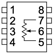
The MCP4151-502E/P is an 8-pin device. The pinout and descriptions are as follows:

Pin Number Pin Name Description
1 CS Chip Select: Activates the SPI communication when pulled low.
2 SCK Serial Clock: Clock signal for SPI communication.
3 SDI Serial Data Input: Data input for SPI communication.
4 VSS Ground: Connect to the system ground.
5 PW0 Terminal 0 of the potentiometer.
6 PW1 Terminal 1 of the potentiometer.
7 VW Wiper Terminal: Adjustable output terminal of the potentiometer.
8 VDD Power Supply: Connect to a voltage source (2.7V to 5.5V).

Usage Instructions

How to Use the MCP4151-502E/P in a Circuit

  1. Power Supply: Connect the VDD pin to a stable voltage source (2.7V to 5.5V) and the VSS pin to ground.
  2. SPI Communication:
    • Connect the CS, SCK, and SDI pins to the corresponding SPI pins on your microcontroller.
    • Ensure the SPI clock speed does not exceed 10MHz.
  3. Potentiometer Terminals:
    • Connect PW0 and PW1 to the desired circuit points where the resistance needs to be adjusted.
    • The VW pin provides the adjustable wiper output.
  4. Programming the Wiper:
    • Use SPI commands to set the wiper position (0 to 255). Each step corresponds to approximately 19.6Ω (5kΩ ÷ 256).

Important Considerations

  • Power-Up State: On power-up, the wiper position defaults to mid-scale (position 128).
  • SPI Configuration: Ensure the SPI mode is set to Mode 0 (CPOL = 0, CPHA = 0).
  • Current Limitation: Do not exceed the maximum wiper current of ±2.5mA to avoid damaging the device.
  • Bypass Capacitor: Place a 0.1µF ceramic capacitor close to the VDD pin to stabilize the power supply.

Example: Using MCP4151-502E/P with Arduino UNO

Below is an example of how to control the MCP4151-502E/P using an Arduino UNO:

#include <SPI.h>

// Define MCP4151 pins
const int CS_PIN = 10; // Chip Select pin connected to Arduino pin 10

void setup() {
  // Initialize SPI communication
  SPI.begin();
  pinMode(CS_PIN, OUTPUT);
  digitalWrite(CS_PIN, HIGH); // Ensure CS is initially high
}

void loop() {
  setWiperPosition(128); // Set wiper to mid-scale (128 out of 256)
  delay(1000);           // Wait for 1 second
  setWiperPosition(64);  // Set wiper to 1/4 scale (64 out of 256)
  delay(1000);           // Wait for 1 second
}

// Function to set the wiper position
void setWiperPosition(byte position) {
  digitalWrite(CS_PIN, LOW); // Select the MCP4151
  SPI.transfer(0x00);        // Command byte: Write to wiper register
  SPI.transfer(position);    // Data byte: Wiper position (0-255)
  digitalWrite(CS_PIN, HIGH); // Deselect the MCP4151
}

Troubleshooting and FAQs

Common Issues

  1. No Response from the MCP4151:

    • Ensure the CS pin is correctly toggled (LOW during communication, HIGH otherwise).
    • Verify the SPI clock speed is within the 10MHz limit.
    • Check all connections, especially the power supply and ground.
  2. Incorrect Wiper Position:

    • Confirm the SPI mode is set to Mode 0 (CPOL = 0, CPHA = 0).
    • Ensure the data sent to the MCP4151 is within the valid range (0 to 255).
  3. Device Overheating:

    • Check that the wiper current does not exceed ±2.5mA.
    • Verify the power supply voltage is within the 2.7V to 5.5V range.

FAQs

Q: Can the MCP4151-502E/P be used as a variable resistor?
A: Yes, by connecting one of the fixed terminals (PW0 or PW1) and the wiper (VW), the MCP4151 can function as a variable resistor.

Q: What happens to the wiper position after a power cycle?
A: The wiper position resets to the mid-scale value (position 128) after a power cycle.

Q: Can I use the MCP4151 with a 3.3V microcontroller?
A: Yes, the MCP4151 operates with a supply voltage range of 2.7V to 5.5V, making it compatible with 3.3V systems.

Q: Is the MCP4151-502E/P suitable for audio applications?
A: Yes, its precise resistance adjustment and low noise make it suitable for audio volume control and other signal conditioning tasks.