How to Use SX1276 Lora: Examples, Pinouts, and Specs
Introduction
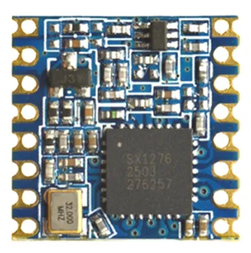
The SX1276 is a low-power, long-range transceiver designed for LoRa (Long Range) and FSK (Frequency Shift Keying) modulation. It operates in the sub-GHz frequency bands (137 MHz to 1020 MHz) and is widely used in IoT applications for wireless communication. The SX1276 offers high sensitivity, robust performance, and excellent interference immunity, making it ideal for applications requiring reliable data transmission over long distances in challenging environments.
Explore Projects Built with SX1276 Lora


Explore Projects Built with SX1276 Lora
Common Applications
- Internet of Things (IoT) devices
- Smart metering (e.g., water, gas, electricity)
- Industrial automation and monitoring
- Agricultural monitoring systems
- Asset tracking and geolocation
- Wireless sensor networks
Technical Specifications
The SX1276 is a highly versatile transceiver with the following key specifications:
| Parameter | Value |
|---|---|
| Frequency Range | 137 MHz to 1020 MHz |
| Modulation Techniques | LoRa, FSK, GFSK, MSK, GMSK, OOK |
| Sensitivity | Down to -148 dBm (LoRa mode) |
| Output Power | Up to +20 dBm (100 mW) |
| Data Rate | LoRa: 0.018 kbps to 37.5 kbps; FSK: 1.2 kbps to 300 kbps |
| Supply Voltage | 1.8 V to 3.7 V |
| Current Consumption | 10.3 mA (Rx mode), 120 mA (Tx mode at +20 dBm) |
| Operating Temperature Range | -40°C to +85°C |
| Communication Interface | SPI (Serial Peripheral Interface) |
| Package Type | QFN-28 (5 mm x 5 mm) |
Pin Configuration and Descriptions
The SX1276 has 28 pins, with the key pin functions described below:
| Pin Number | Pin Name | Description |
|---|---|---|
| 1 | GND | Ground connection |
| 2 | RFIO | RF input/output for the antenna |
| 3 | VDD | Power supply input (1.8 V to 3.7 V) |
| 4 | DIO0 | Digital I/O pin 0 (used for interrupts or status signaling) |
| 5 | DIO1 | Digital I/O pin 1 (used for interrupts or status signaling) |
| 6 | DIO2 | Digital I/O pin 2 (used for interrupts or status signaling) |
| 7 | DIO3 | Digital I/O pin 3 (used for interrupts or status signaling) |
| 8 | DIO4 | Digital I/O pin 4 (used for interrupts or status signaling) |
| 9 | DIO5 | Digital I/O pin 5 (used for interrupts or status signaling) |
| 10 | NSS | SPI chip select (active low) |
| 11 | SCK | SPI clock input |
| 12 | MOSI | SPI master-out, slave-in |
| 13 | MISO | SPI master-in, slave-out |
| 14 | RESET | Reset pin (active low) |
| 15-28 | NC | Not connected |
Usage Instructions
How to Use the SX1276 in a Circuit
- Power Supply: Connect the VDD pin to a stable power source (1.8 V to 3.7 V) and GND to ground.
- Antenna Connection: Connect an appropriate antenna to the RFIO pin for wireless communication.
- SPI Communication: Interface the SX1276 with a microcontroller using the SPI pins (NSS, SCK, MOSI, MISO).
- Interrupts: Use the DIO pins to handle interrupts or status signals from the SX1276.
- Reset: Connect the RESET pin to the microcontroller for initializing the SX1276.
Important Considerations
- Use proper decoupling capacitors near the VDD pin to ensure stable operation.
- Match the antenna impedance (typically 50 ohms) for optimal RF performance.
- Configure the modulation parameters (e.g., frequency, bandwidth, spreading factor) based on your application requirements.
- Ensure compliance with local regulations for operating in the sub-GHz frequency bands.
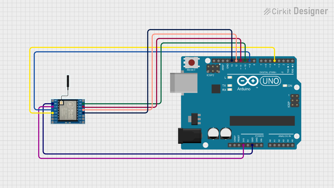
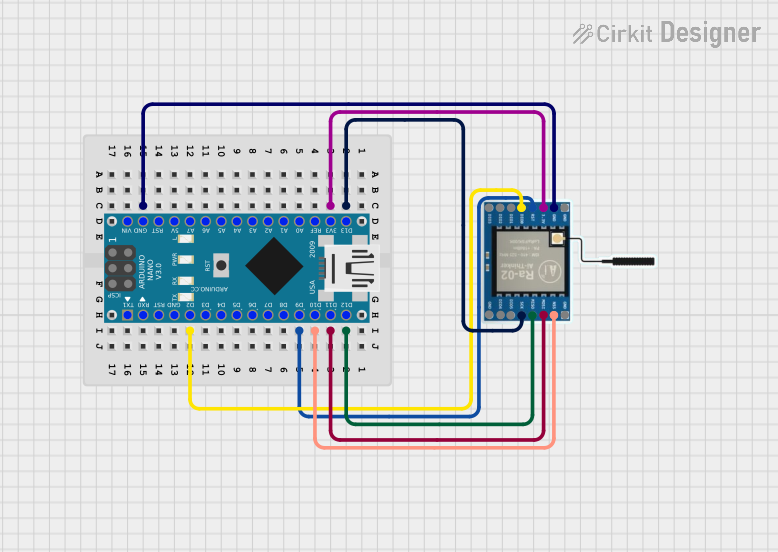
Example: Connecting SX1276 to Arduino UNO
Below is an example of how to connect the SX1276 to an Arduino UNO and send data using LoRa.
Wiring Diagram
| SX1276 Pin | Arduino UNO Pin |
|---|---|
| VDD | 3.3V |
| GND | GND |
| NSS | D10 |
| SCK | D13 |
| MOSI | D11 |
| MISO | D12 |
| RESET | D9 |
| DIO0 | D2 |
Arduino Code Example
#include <SPI.h>
#include <LoRa.h> // Include the LoRa library

#define NSS 10    // Chip select pin
#define RESET 9   // Reset pin
#define DIO0 2    // Interrupt pin

void setup() {
  Serial.begin(9600); // Initialize serial communication
  while (!Serial);

  Serial.println("Initializing LoRa...");

  // Initialize LoRa module
  LoRa.setPins(NSS, RESET, DIO0);
  if (!LoRa.begin(915E6)) { // Set frequency to 915 MHz
    Serial.println("LoRa initialization failed!");
    while (1);
  }

  Serial.println("LoRa initialized successfully!");
}

void loop() {
  Serial.println("Sending packet...");
  LoRa.beginPacket();          // Start a new LoRa packet
  LoRa.print("Hello, LoRa!");  // Add data to the packet
  LoRa.endPacket();            // Send the packet

  delay(5000); // Wait 5 seconds before sending the next packet
}
Notes
- Install the
LoRalibrary in the Arduino IDE before uploading the code. - Adjust the frequency (
915E6in the example) to match your region's regulations.
Troubleshooting and FAQs
Common Issues
No Communication Between Devices
- Ensure the SPI connections are correct and secure.
- Verify that both devices are configured to use the same frequency and modulation parameters.
Low Signal Strength
- Check the antenna connection and ensure it is properly matched to 50 ohms.
- Avoid placing the SX1276 near sources of RF interference.
High Power Consumption
- Ensure the SX1276 is in sleep mode when not actively transmitting or receiving.
- Use a low-power microcontroller to minimize overall power usage.
LoRa Initialization Fails
- Verify the wiring and ensure the NSS, RESET, and DIO0 pins are correctly connected.
- Check the power supply voltage and ensure it is within the specified range.
FAQs
Q: Can the SX1276 operate in both LoRa and FSK modes?
A: Yes, the SX1276 supports both LoRa and FSK modulation, allowing flexibility for different applications.
Q: What is the maximum range of the SX1276?
A: The range depends on factors such as antenna design, transmission power, and environmental conditions. In ideal conditions, the range can exceed 10 km.
Q: Is the SX1276 compatible with Arduino?
A: Yes, the SX1276 can be easily interfaced with Arduino boards using the SPI interface and libraries like LoRa.
Q: How do I reduce interference in my LoRa network?
A: Use different frequencies or spreading factors for devices in the same area to minimize interference.