How to Use E72-2G4M20S1E (CC2652P): Examples, Pinouts, and Specs
Introduction
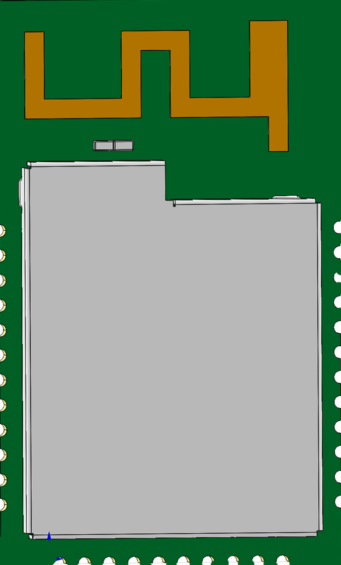
The E72-2G4M20S1E is a compact, low-power wireless module developed by Ebyte Electronic Technology Co., Ltd.. It is based on the CC2652P chip from Texas Instruments, which integrates a powerful ARM Cortex-M4F processor and a high-performance RF core. This module supports multiple wireless communication protocols, including Bluetooth Low Energy (BLE), Zigbee, and Thread, making it ideal for Internet of Things (IoT) applications.
Explore Projects Built with E72-2G4M20S1E (CC2652P)


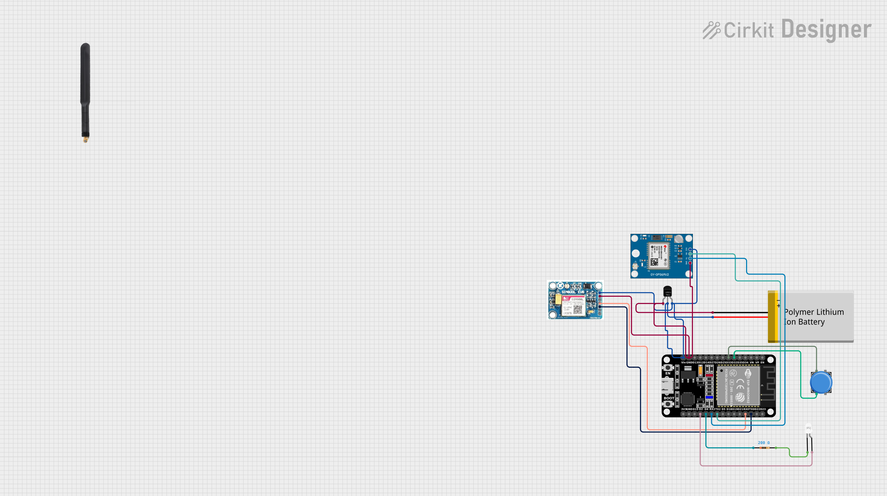
Explore Projects Built with E72-2G4M20S1E (CC2652P)
Common Applications and Use Cases
- Smart Home Devices: Zigbee-based smart lighting, thermostats, and security systems.
- Industrial IoT: Wireless sensor networks and industrial automation.
- Wearable Devices: BLE-enabled fitness trackers and health monitoring systems.
- Wireless Communication Gateways: Zigbee-to-Wi-Fi or BLE-to-Wi-Fi bridges.
- Mesh Networking: Applications requiring robust and scalable wireless communication.
Technical Specifications
Key Technical Details
| Parameter | Value |
|---|---|
| Chipset | CC2652P (Texas Instruments) |
| Wireless Protocols | BLE 5.0, Zigbee 3.0, Thread, IEEE 802.15.4 |
| Operating Frequency | 2.4 GHz |
| Output Power | Up to +20 dBm (adjustable) |
| Sensitivity | -100 dBm (BLE), -104 dBm (Zigbee) |
| Operating Voltage | 1.8V to 3.8V |
| Current Consumption | 7.4 mA (RX), 24.5 mA (TX @ +20 dBm) |
| Operating Temperature | -40°C to +85°C |
| Dimensions | 22 mm x 13 mm x 2.3 mm |
| Antenna Options | PCB antenna or external antenna (IPEX) |
Pin Configuration and Descriptions
The E72-2G4M20S1E module has 32 pins. Below is the pinout description:
| Pin Number | Pin Name | Description |
|---|---|---|
| 1 | GND | Ground |
| 2 | VCC | Power supply (1.8V to 3.8V) |
| 3 | DIO_0 | General-purpose I/O or RF control |
| 4 | DIO_1 | General-purpose I/O |
| 5 | DIO_2 | General-purpose I/O |
| 6 | DIO_3 | General-purpose I/O |
| 7 | DIO_4 | General-purpose I/O |
| 8 | DIO_5 | General-purpose I/O |
| 9 | DIO_6 | General-purpose I/O |
| 10 | DIO_7 | General-purpose I/O |
| 11 | RESET | Reset pin (active low) |
| 12 | SWD_CLK | Debug clock (for programming/debugging) |
| 13 | SWD_IO | Debug data (for programming/debugging) |
| 14 | RF_N | RF signal (connect to external antenna) |
| 15 | RF_P | RF signal (connect to external antenna) |
| 16-32 | Reserved | Reserved for future use |
Note: For detailed pin mapping and alternate functions, refer to the official datasheet.
Usage Instructions
How to Use the Component in a Circuit
- Power Supply: Connect the VCC pin to a regulated power source (1.8V to 3.8V) and GND to ground.
- Antenna Connection: Use the onboard PCB antenna or connect an external antenna via the IPEX connector for better range.
- Programming and Debugging: Use the SWD_CLK and SWD_IO pins to program the module using a compatible debugger (e.g., J-Link or XDS110).
- GPIO Configuration: Configure the DIO pins as needed for your application (e.g., input, output, or alternate functions).
- Protocol Selection: Use the appropriate firmware to enable BLE, Zigbee, or Thread communication.
Important Considerations and Best Practices
- Power Supply Stability: Ensure a stable power supply with minimal noise to avoid communication issues.
- Antenna Placement: For optimal RF performance, place the antenna away from metal objects and other sources of interference.
- Firmware Updates: Use the latest firmware provided by Ebyte or Texas Instruments to ensure compatibility and performance.
- Heat Dissipation: If operating at high output power (+20 dBm), ensure proper heat dissipation to avoid thermal issues.
Example: Using with Arduino UNO (BLE Communication)
Below is an example of how to use the E72-2G4M20S1E module with an Arduino UNO for BLE communication.
Circuit Connection
| E72-2G4M20S1E Pin | Arduino UNO Pin |
|---|---|
| VCC | 3.3V |
| GND | GND |
| DIO_0 (TX) | RX (Pin 0) |
| DIO_1 (RX) | TX (Pin 1) |
Arduino Code
#include <SoftwareSerial.h>

// Define RX and TX pins for communication with the module
SoftwareSerial BLEModule(0, 1); // RX = Pin 0, TX = Pin 1

void setup() {
  // Initialize serial communication with the module
  BLEModule.begin(9600);
  Serial.begin(9600); // For debugging via Serial Monitor

  // Send initialization command to the module
  BLEModule.println("AT+RESET");
  delay(1000); // Wait for the module to reset
  Serial.println("Module initialized.");
}

void loop() {
  // Check if data is available from the module
  if (BLEModule.available()) {
    String data = BLEModule.readString();
    Serial.println("Received from module: " + data);
  }

  // Send data to the module
  BLEModule.println("Hello from Arduino!");
  delay(2000); // Wait 2 seconds before sending again
}
Note: Replace the
AT+RESETcommand with the appropriate AT commands for your application.
Troubleshooting and FAQs
Common Issues and Solutions
No Communication with the Module:
- Cause: Incorrect wiring or baud rate mismatch.
- Solution: Double-check the connections and ensure the baud rate matches the module's configuration.
Poor RF Performance:
- Cause: Antenna placement or interference.
- Solution: Reposition the antenna and ensure it is not obstructed by metal objects.
Module Overheating:
- Cause: High output power without proper heat dissipation.
- Solution: Reduce the output power or improve heat dissipation.
Firmware Update Fails:
- Cause: Incorrect programming tool or connection.
- Solution: Use a compatible debugger and verify the SWD connections.
FAQs
Q: Can the module operate on 5V?
- A: No, the module operates within a voltage range of 1.8V to 3.8V. Use a voltage regulator if needed.
Q: Does the module support Wi-Fi?
- A: No, the module supports BLE, Zigbee, and Thread but not Wi-Fi.
Q: How do I switch between BLE and Zigbee?
- A: The communication protocol is determined by the firmware. Flash the appropriate firmware to switch protocols.
Q: Can I use this module for mesh networking?
- A: Yes, the module supports Zigbee and Thread, which are ideal for mesh networking applications.