How to Use Buck Boost Converter: Examples, Pinouts, and Specs
Introduction
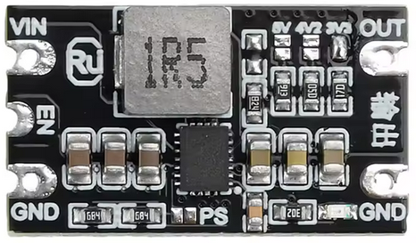
The DIYMORE CR-SJ5530 Buck Boost Converter is a versatile DC-DC converter capable of stepping up (boosting) or stepping down (bucking) an input voltage to achieve a stable and desired output voltage. This flexibility makes it an essential component in power supply applications where input voltage may vary but a constant output voltage is required.
Explore Projects Built with Buck Boost Converter


Explore Projects Built with Buck Boost Converter
Common Applications
- Battery-powered devices where input voltage fluctuates (e.g., lithium-ion batteries)
- Solar power systems
- LED drivers
- Portable electronics
- Embedded systems requiring stable voltage for microcontrollers or sensors
Technical Specifications
The following table outlines the key technical details of the CR-SJ5530 Buck Boost Converter:
| Parameter | Value |
|---|---|
| Input Voltage Range | 5V to 30V |
| Output Voltage Range | 1.2V to 30V (adjustable) |
| Output Current | Up to 4A |
| Output Power | Maximum 35W |
| Efficiency | Up to 92% |
| Switching Frequency | 150 kHz |
| Operating Temperature | -40°C to +85°C |
| Dimensions | 48mm x 25mm x 14mm |
Pin Configuration and Descriptions
The CR-SJ5530 module has the following pin layout:
| Pin Name | Description |
|---|---|
| VIN+ | Positive input voltage terminal (connect to the power source) |
| VIN- | Negative input voltage terminal (connect to the ground of the power source) |
| VOUT+ | Positive output voltage terminal (connect to the load) |
| VOUT- | Negative output voltage terminal (connect to the ground of the load) |
| Potentiometer | Adjustable knob to set the desired output voltage |
Usage Instructions
How to Use the Component in a Circuit
- Connect the Input Voltage:
- Attach the positive terminal of your power source to the
VIN+pin. - Attach the ground terminal of your power source to the
VIN-pin.
- Attach the positive terminal of your power source to the
- Connect the Load:
- Connect the positive terminal of your load to the
VOUT+pin. - Connect the ground terminal of your load to the
VOUT-pin.
- Connect the positive terminal of your load to the
- Adjust the Output Voltage:
- Use the onboard potentiometer to set the desired output voltage. Turn clockwise to increase the voltage and counterclockwise to decrease it.
- Verify the Output:
- Use a multimeter to measure the output voltage across
VOUT+andVOUT-to ensure it matches your requirements before connecting sensitive devices.
- Use a multimeter to measure the output voltage across
Important Considerations and Best Practices
- Input Voltage Range: Ensure the input voltage is within the specified range (5V to 30V). Exceeding this range may damage the module.
- Output Voltage Adjustment: Always adjust the output voltage without a load connected to avoid overvoltage damage to your device.
- Heat Dissipation: For high-power applications, ensure proper ventilation or use a heatsink to prevent overheating.
- Polarity: Double-check the polarity of connections to avoid damaging the module.
- Current Limitation: Do not exceed the maximum output current of 4A to prevent overloading.
Example: Using with Arduino UNO
The CR-SJ5530 can be used to power an Arduino UNO with a stable 5V output. Below is an example setup:
- Connect a 12V DC power source to the
VIN+andVIN-pins of the converter. - Adjust the potentiometer to set the output voltage to 5V.
- Connect the
VOUT+pin to the Arduino's5Vpin and theVOUT-pin to the Arduino'sGNDpin.
Here is an example Arduino code to blink an LED, powered by the Buck Boost Converter:
// Simple LED Blink Example
// Ensure the Buck Boost Converter is set to output 5V for the Arduino UNO.

const int ledPin = 13; // Pin connected to the onboard LED

void setup() {
  pinMode(ledPin, OUTPUT); // Set the LED pin as an output
}

void loop() {
  digitalWrite(ledPin, HIGH); // Turn the LED on
  delay(1000);                // Wait for 1 second
  digitalWrite(ledPin, LOW);  // Turn the LED off
  delay(1000);                // Wait for 1 second
}
Troubleshooting and FAQs
Common Issues and Solutions
No Output Voltage:
- Cause: Incorrect input connections or insufficient input voltage.
- Solution: Verify the polarity of the input connections and ensure the input voltage is within the 5V to 30V range.
Output Voltage Fluctuates:
- Cause: Load exceeds the maximum current rating or unstable input voltage.
- Solution: Reduce the load current or stabilize the input voltage using a capacitor.
Module Overheats:
- Cause: High power operation without proper cooling.
- Solution: Add a heatsink or improve ventilation around the module.
Cannot Adjust Output Voltage:
- Cause: Faulty potentiometer or incorrect adjustment procedure.
- Solution: Ensure the potentiometer is not damaged and adjust it slowly while monitoring the output voltage.
FAQs
Q: Can I use this module to charge a battery?
- A: Yes, but ensure the output voltage and current are set according to the battery's specifications.
Q: What happens if I reverse the input polarity?
- A: The module does not have reverse polarity protection, so reversing the input polarity may permanently damage it.
Q: Can I use this module with a solar panel?
- A: Yes, the module can regulate the variable output of a solar panel to a stable voltage for your load.
Q: Is the output voltage stable under varying loads?
- A: Yes, the module is designed to provide a stable output voltage as long as the load does not exceed the maximum current rating.
This concludes the documentation for the DIYMORE CR-SJ5530 Buck Boost Converter.