
How to Use 5 mm RGB LED, Common Cathode (R-G-B Pin Order): Examples, Pinouts, and Specs
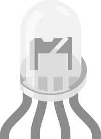
 Design with 5 mm RGB LED, Common Cathode (R-G-B Pin Order) in Cirkit Designer
Introduction
The 5 mm RGB LED is a versatile light-emitting diode capable of producing red, green, and blue light. By combining these primary colors at varying intensities, it can generate a wide spectrum of colors. This component is widely used in decorative lighting, status indicators, displays, and DIY electronics projects. The common cathode configuration simplifies wiring by sharing a single cathode (negative terminal) for all three colors, while each color has its own anode (positive terminal) for independent control.
Explore Projects Built with 5 mm RGB LED, Common Cathode (R-G-B Pin Order)
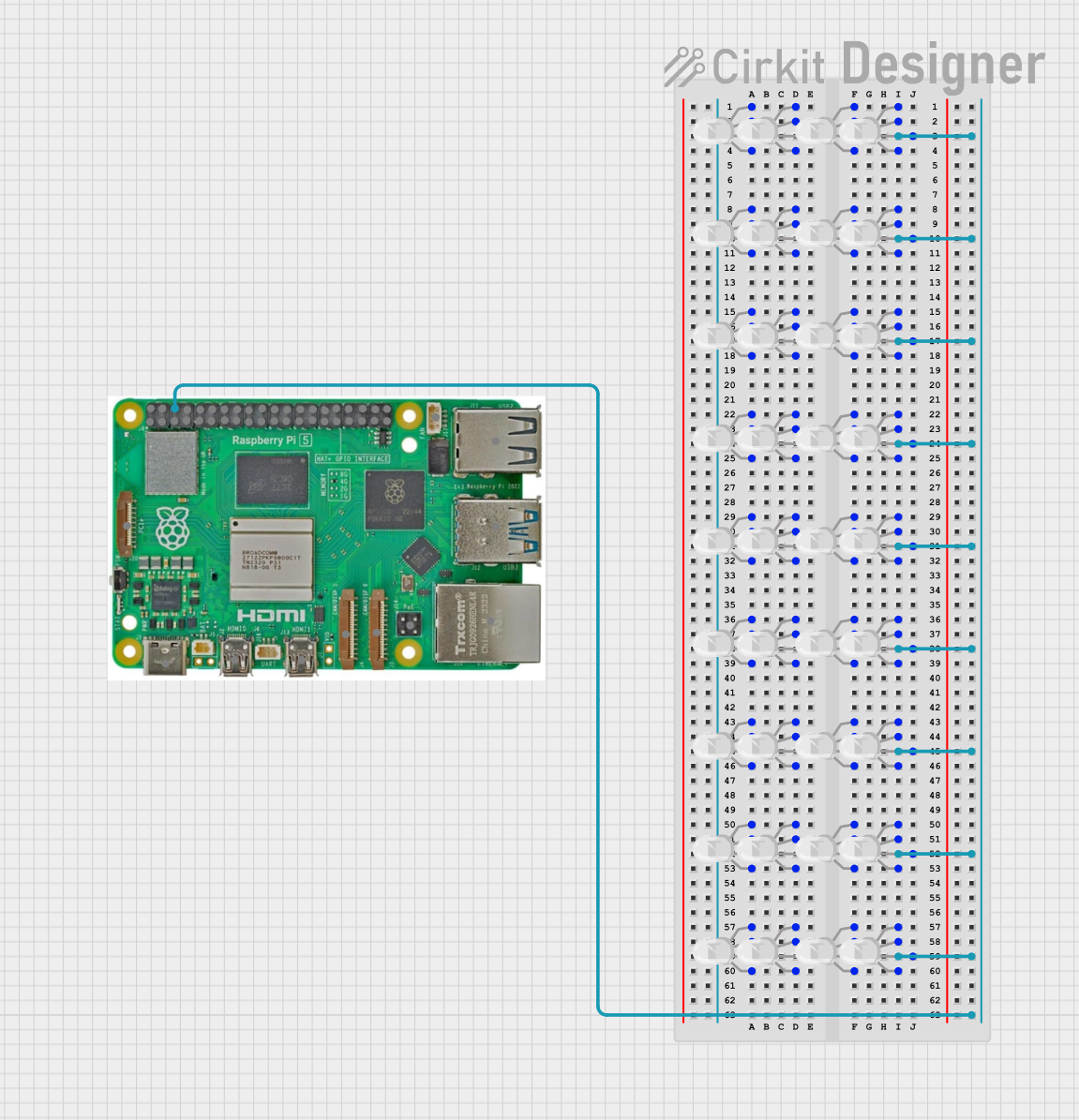 Open Project in Cirkit Designer
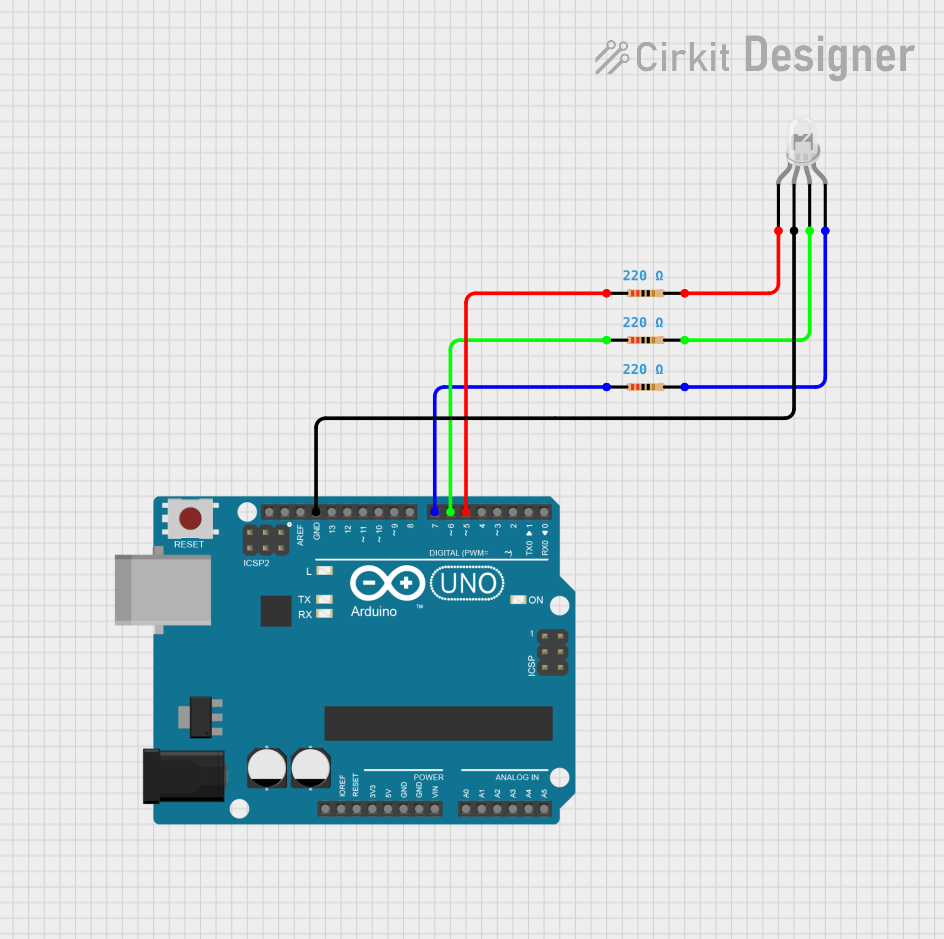 Open Project in Cirkit Designer
 Open Project in Cirkit Designer
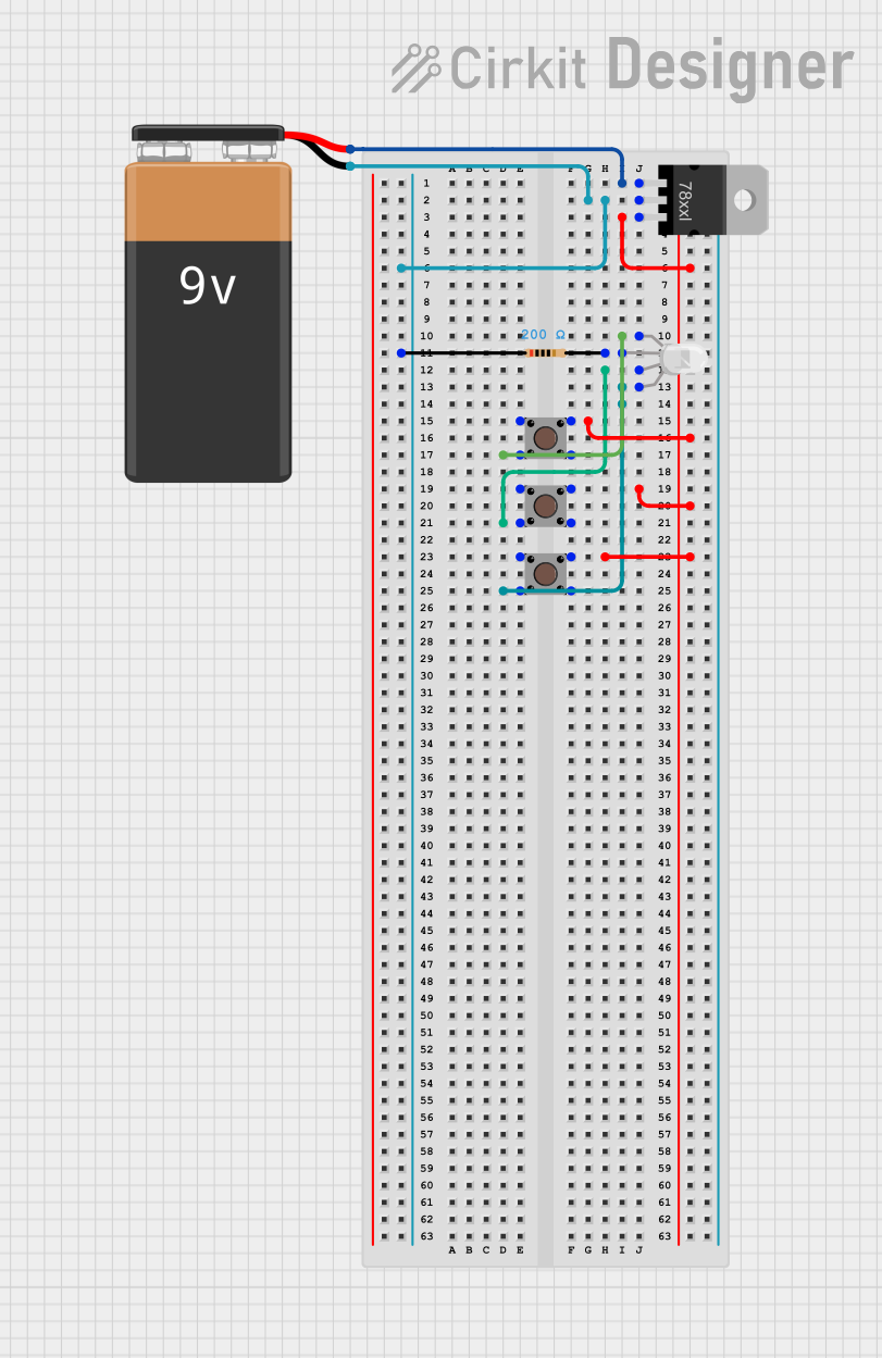 Open Project in Cirkit Designer
Explore Projects Built with 5 mm RGB LED, Common Cathode (R-G-B Pin Order)
Open Project in Cirkit DesignerOpen Project in Cirkit DesignerOpen Project in Cirkit DesignerOpen Project in Cirkit DesignerTechnical Specifications
- Type: 5 mm RGB LED (Common Cathode)
- Forward Voltage:
- Red: 2.0V - 2.4V
- Green: 3.0V - 3.4V
- Blue: 3.0V - 3.4V
- Forward Current: 20 mA (per color)
- Maximum Power Dissipation: 75 mW (per color)
- Viewing Angle: 20° - 30°
- Pin Order: R-G-B (Red, Green, Blue) with a shared cathode
- Package Size: 5 mm diameter
Pin Configuration and Descriptions
| Pin Number | Pin Name | Description |
|---|---|---|
| 1 | Red | Anode for the red LED |
| 2 | Cathode | Common cathode (negative terminal) |
| 3 | Green | Anode for the green LED |
| 4 | Blue | Anode for the blue LED |
Usage Instructions
How to Use the Component in a Circuit
Wiring:
- Connect the cathode (Pin 2) to the ground (GND) of your power supply or microcontroller.
- Connect each anode (Pins 1, 3, and 4) to a current-limiting resistor before connecting to the power source or microcontroller pins.
- Use resistors with appropriate values (e.g., 220Ω to 330Ω) to limit the current to 20 mA per color.
Controlling Colors:
- To light up a specific color, apply a voltage to the corresponding anode.
- To mix colors, apply voltages to multiple anodes simultaneously. For example:
- Red + Green = Yellow
- Green + Blue = Cyan
- Red + Blue = Magenta
- Red + Green + Blue = White
PWM for Brightness Control:
- Use Pulse Width Modulation (PWM) to control the brightness of each color and create smooth color transitions.
Example Circuit with Arduino UNO
Below is an example of how to connect and control the 5 mm RGB LED using an Arduino UNO:
Circuit Diagram
- Connect:
- Pin 1 (Red) to Arduino digital pin 9 through a 220Ω resistor.
- Pin 3 (Green) to Arduino digital pin 10 through a 220Ω resistor.
- Pin 4 (Blue) to Arduino digital pin 11 through a 220Ω resistor.
- Pin 2 (Cathode) to Arduino GND.
Arduino Code
// Define pins for RGB LED
const int redPin = 9;    // Red anode connected to pin 9
const int greenPin = 10; // Green anode connected to pin 10
const int bluePin = 11;  // Blue anode connected to pin 11

void setup() {
  // Set RGB pins as output
  pinMode(redPin, OUTPUT);
  pinMode(greenPin, OUTPUT);
  pinMode(bluePin, OUTPUT);
}

void loop() {
  // Example: Cycle through basic colors
  setColor(255, 0, 0); // Red
  delay(1000);
  setColor(0, 255, 0); // Green
  delay(1000);
  setColor(0, 0, 255); // Blue
  delay(1000);
  setColor(255, 255, 0); // Yellow
  delay(1000);
  setColor(0, 255, 255); // Cyan
  delay(1000);
  setColor(255, 0, 255); // Magenta
  delay(1000);
  setColor(255, 255, 255); // White
  delay(1000);
}

// Function to set RGB color
void setColor(int redValue, int greenValue, int blueValue) {
  analogWrite(redPin, redValue);   // Set brightness for red
  analogWrite(greenPin, greenValue); // Set brightness for green
  analogWrite(bluePin, blueValue);  // Set brightness for blue
}
Important Considerations and Best Practices
- Always use current-limiting resistors to prevent damage to the LED.
- Avoid exceeding the maximum forward current (20 mA per color).
- Ensure proper heat dissipation if the LED is used at high brightness for extended periods.
- Use PWM for smooth color transitions and brightness control.
Troubleshooting and FAQs
Common Issues and Solutions
LED Not Lighting Up:
- Check the wiring and ensure the cathode is connected to GND.
- Verify that the anodes are connected to the correct pins and resistors.
- Ensure the power supply voltage matches the LED's forward voltage requirements.
Incorrect Colors or No Color Mixing:
- Verify the pin connections (R-G-B order).
- Check the resistor values to ensure consistent current for all colors.
LED Flickering:
- If using PWM, ensure the frequency is high enough to avoid visible flicker.
- Check for loose connections or unstable power supply.
LED Overheating:
- Reduce the current by increasing the resistor values.
- Avoid running the LED at maximum brightness for prolonged periods.
FAQs
Can I use the RGB LED without a microcontroller? Yes, you can use switches or a simple circuit with resistors to manually control the colors.
What resistor value should I use? A 220Ω to 330Ω resistor is typically sufficient for 5V systems. Calculate the exact value using Ohm's Law:
R = (V_supply - V_forward) / I_forward.Can I control the LED with 3.3V systems? Yes, but ensure the forward voltage of each color is compatible with the 3.3V supply.