How to Use 5 Inch HMI LCD Module Model: DMG80480C050_03W: Examples, Pinouts, and Specs
Introduction
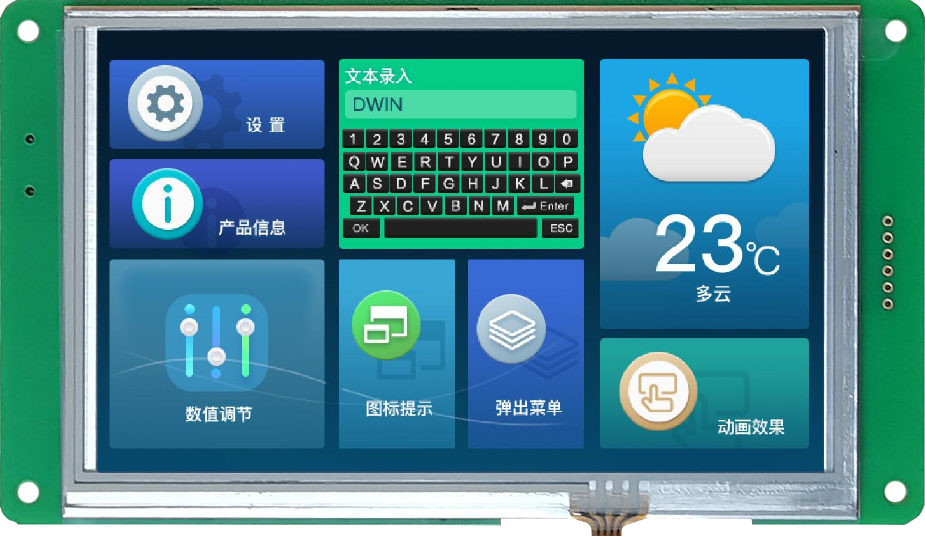
The DMG80480C050_03W is a 5-inch Human-Machine Interface (HMI) LCD module manufactured by DWIN. It features an 800x480 pixel resolution and is designed for seamless user interaction in embedded systems. This module typically includes touch functionality, enabling users to control devices through an intuitive graphical interface. Its compact size and robust design make it ideal for industrial, medical, and consumer electronics applications.
Explore Projects Built with 5 Inch HMI LCD Module Model: DMG80480C050_03W


Explore Projects Built with 5 Inch HMI LCD Module Model: DMG80480C050_03W
Common Applications and Use Cases
- Industrial control panels
- Home automation systems
- Medical devices with touch-based interfaces
- Consumer electronics such as smart appliances
- Automotive dashboards and infotainment systems
Technical Specifications
Key Technical Details
| Parameter | Specification |
|---|---|
| Display Size | 5 inches |
| Resolution | 800 x 480 pixels (WVGA) |
| Touch Panel | Capacitive or Resistive (varies) |
| Operating Voltage | 5V DC |
| Communication Interface | UART (TTL) |
| Operating Temperature | -20°C to 70°C |
| Storage Temperature | -30°C to 80°C |
| Backlight | LED |
| Brightness | 250 cd/m² |
| Viewing Angle | 70°/70°/50°/70° (L/R/U/D) |
| Flash Memory | 16MB |
| Processor | T5L ASIC (DWIN proprietary) |
Pin Configuration and Descriptions
| Pin Number | Pin Name | Description |
|---|---|---|
| 1 | VCC | Power supply input (5V DC) |
| 2 | GND | Ground |
| 3 | RXD | UART Receive Data (connect to TX of host MCU) |
| 4 | TXD | UART Transmit Data (connect to RX of host MCU) |
| 5 | NC | Not Connected |
| 6 | NC | Not Connected |
Usage Instructions
How to Use the Component in a Circuit
- Power Supply: Connect the VCC pin to a stable 5V DC power source and the GND pin to the ground of your circuit.
- UART Communication: Use the RXD and TXD pins to establish a UART connection with your microcontroller or host device. Ensure the baud rate matches the module's default setting (typically 115200 bps).
- Touch Interface: Load a pre-designed graphical user interface (GUI) onto the module using DWIN's development tools (e.g., DGUS software). The GUI can include buttons, sliders, and other interactive elements.
- Programming: Use the UART interface to send commands or data to the module. The module processes these commands and updates the display accordingly.
Important Considerations and Best Practices
- Power Stability: Ensure the power supply is stable and free from noise to avoid display flickering or malfunction.
- UART Configuration: Verify the UART settings (baud rate, parity, stop bits) on both the module and the host device.
- GUI Design: Use DWIN's DGUS development tools to create and upload GUI designs. Follow the manufacturer's guidelines for optimal performance.
- ESD Protection: Implement proper electrostatic discharge (ESD) protection to safeguard the module during handling and operation.
- Firmware Updates: Periodically check for firmware updates from DWIN to ensure compatibility and access to new features.
Example Code for Arduino UNO
Below is an example of how to interface the DMG80480C050_03W with an Arduino UNO using UART communication:
#include <SoftwareSerial.h>

// Define RX and TX pins for SoftwareSerial
SoftwareSerial HMI(10, 11); // RX = Pin 10, TX = Pin 11

void setup() {
  // Initialize serial communication with the HMI module
  HMI.begin(115200); // Set baud rate to 115200
  Serial.begin(9600); // For debugging via Serial Monitor

  // Send initialization command to the HMI module
  HMI.print("Initialization Command\r\n");
  // Replace with actual command based on your GUI design
}

void loop() {
  // Check if data is available from the HMI module
  if (HMI.available()) {
    String data = HMI.readString(); // Read data from HMI
    Serial.println("Data from HMI: " + data); // Print to Serial Monitor
  }

  // Example: Send a command to update a GUI element
  HMI.print("Update Command\r\n");
  // Replace with actual command for your application
  delay(1000); // Delay for demonstration purposes
}
Notes:
- Replace
"Initialization Command"and"Update Command"with actual commands based on your GUI design and the DWIN protocol. - Ensure the RX and TX pins on the Arduino are correctly connected to the TXD and RXD pins on the HMI module.
Troubleshooting and FAQs
Common Issues and Solutions
Display Not Turning On
- Cause: Insufficient or unstable power supply.
- Solution: Verify the power source provides a stable 5V DC. Check connections to the VCC and GND pins.
No Communication Between HMI and Host Device
- Cause: Incorrect UART settings or wiring.
- Solution: Ensure the baud rate, parity, and stop bits match on both devices. Double-check the RXD and TXD connections.
Touch Panel Not Responding
- Cause: Faulty touch calibration or hardware issue.
- Solution: Recalibrate the touch panel using DWIN's tools. If the issue persists, inspect the hardware for damage.
GUI Not Displaying Correctly
- Cause: Incorrect GUI file or upload error.
- Solution: Re-upload the GUI file using DWIN's DGUS software. Ensure the file format and settings are correct.
FAQs
Q: Can I use this module with a Raspberry Pi?
- A: Yes, the module can be connected to a Raspberry Pi via UART. Use the appropriate GPIO pins for TX and RX communication.
Q: What software is required to design the GUI?
- A: DWIN provides DGUS software for GUI design and development. It is available on their official website.
Q: Is the module compatible with 3.3V logic?
- A: No, the module requires 5V logic levels. Use a level shifter if your host device operates at 3.3V.
Q: How do I update the firmware?
- A: Firmware updates can be performed using a USB-to-UART adapter and DWIN's firmware update tools. Follow the manufacturer's instructions for the update process.