How to Use Relay Module V4.0 DFRobot DFR0017 5V nom. 10A: Examples, Pinouts, and Specs
Introduction
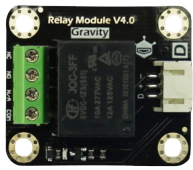
The Relay Module V4.0 (DFR0017) by DFRobot is a versatile 5V relay module designed to control high-power devices using low-power control signals. It is capable of switching loads up to 10A, making it ideal for applications such as home automation, industrial control, and robotics. This module provides an easy interface for microcontrollers like Arduino, Raspberry Pi, and other logic-level devices, enabling seamless integration into various projects.
Explore Projects Built with Relay Module V4.0 DFRobot DFR0017 5V nom. 10A


Explore Projects Built with Relay Module V4.0 DFRobot DFR0017 5V nom. 10A
Common Applications and Use Cases
- Home automation (e.g., controlling lights, fans, or appliances)
- Industrial equipment control
- Robotics and mechatronics
- Smart energy systems
- Prototyping and educational projects
Technical Specifications
Below are the key technical details of the Relay Module V4.0:
| Parameter | Specification |
|---|---|
| Operating Voltage | 5V DC |
| Trigger Voltage | 3.3V to 5V DC |
| Maximum Load Current | 10A |
| Maximum Load Voltage | 250V AC / 30V DC |
| Relay Type | SPDT (Single Pole Double Throw) |
| Dimensions | 38mm x 34mm x 19mm |
| Weight | 20g |
| Isolation | Optocoupler isolation for safety |
Pin Configuration and Descriptions
The module has a total of 6 pins and terminals, as described below:
Signal Pins
| Pin | Name | Description |
|---|---|---|
| 1 | VCC | Power supply input (5V DC) |
| 2 | GND | Ground connection |
| 3 | IN | Control signal input (active HIGH) |
Output Terminals
| Terminal | Name | Description |
|---|---|---|
| 1 | COM | Common terminal for the relay switch |
| 2 | NO | Normally Open terminal (connected when activated) |
| 3 | NC | Normally Closed terminal (connected when idle) |
Usage Instructions
How to Use the Relay Module in a Circuit
- Power the Module: Connect the VCC pin to a 5V DC power source and the GND pin to the ground.
- Control Signal: Connect the IN pin to a digital output pin of your microcontroller. When the control signal is HIGH, the relay will activate.
- Load Connection:
- Connect the device you want to control to the COM terminal.
- Use the NO terminal if you want the device to turn on when the relay is activated.
- Use the NC terminal if you want the device to turn off when the relay is activated.
- Isolation: Ensure proper electrical isolation between the control circuit and the high-power load for safety.
Important Considerations and Best Practices
- Power Supply: Ensure the module is powered with a stable 5V DC supply.
- Load Ratings: Do not exceed the maximum load ratings of 10A and 250V AC / 30V DC.
- Optocoupler Isolation: The module includes optocoupler isolation to protect the control circuit. However, avoid direct contact with high-voltage components.
- Flyback Diode: If controlling inductive loads (e.g., motors), use a flyback diode across the load to prevent voltage spikes.
- Mounting: Secure the module in a well-ventilated area to prevent overheating.
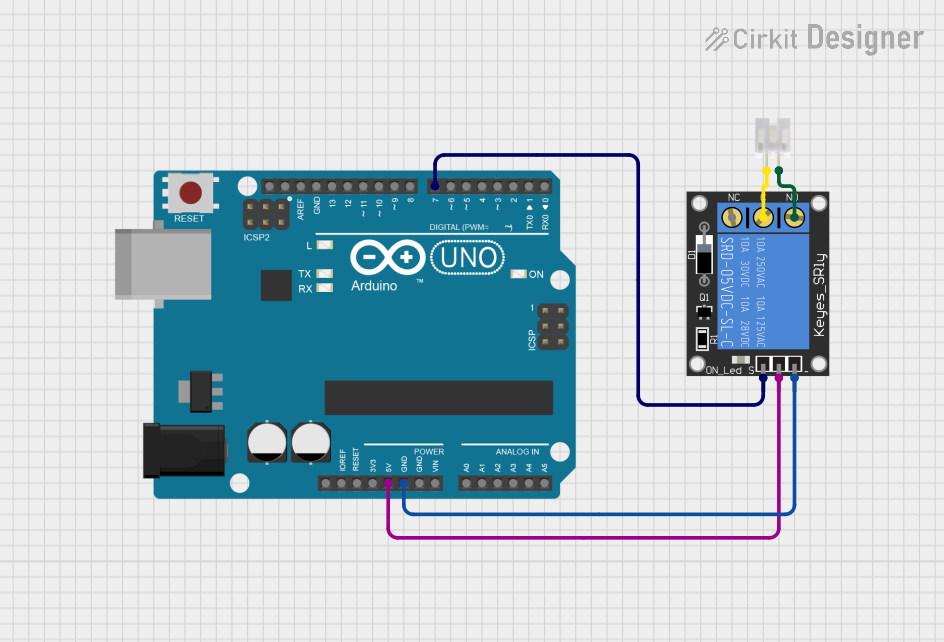
Example: Connecting to an Arduino UNO
Below is an example of how to use the Relay Module V4.0 with an Arduino UNO to control a light bulb.
Circuit Connections
- Connect the relay module's VCC to the Arduino's 5V pin.
- Connect the relay module's GND to the Arduino's GND pin.
- Connect the relay module's IN pin to Arduino digital pin 7.
- Connect the light bulb to the COM and NO terminals of the relay.
Arduino Code
// Example code to control the Relay Module V4.0 with an Arduino UNO

const int relayPin = 7; // Define the pin connected to the relay module

void setup() {
  pinMode(relayPin, OUTPUT); // Set the relay pin as an output
  digitalWrite(relayPin, LOW); // Ensure the relay is off at startup
}

void loop() {
  digitalWrite(relayPin, HIGH); // Turn the relay on (light bulb ON)
  delay(5000); // Wait for 5 seconds
  digitalWrite(relayPin, LOW); // Turn the relay off (light bulb OFF)
  delay(5000); // Wait for 5 seconds
}
Troubleshooting and FAQs
Common Issues and Solutions
Relay Not Activating
- Cause: Insufficient control signal voltage.
- Solution: Ensure the control signal voltage is between 3.3V and 5V.
Load Not Switching
- Cause: Incorrect wiring of the load to the relay terminals.
- Solution: Verify the load is connected to the correct terminals (COM, NO, or NC).
Overheating
- Cause: Exceeding the maximum load current or voltage.
- Solution: Ensure the load does not exceed 10A or 250V AC / 30V DC.
Noise or Flickering
- Cause: Electrical noise or unstable power supply.
- Solution: Use a capacitor across the power supply and ensure proper grounding.
FAQs
Q1: Can I use this relay module with a 3.3V microcontroller?
A1: Yes, the module can be triggered with a 3.3V control signal, but ensure the power supply to the module is 5V.
Q2: Is the relay module safe for high-voltage applications?
A2: Yes, the module is designed for high-voltage applications up to 250V AC. However, always follow safety precautions and ensure proper isolation.
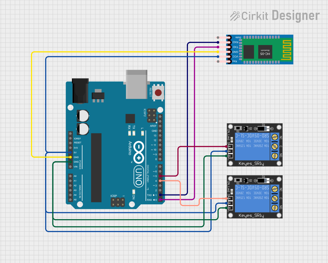
Q3: Can I control multiple relays with one Arduino?
A3: Yes, you can control multiple relays by connecting each relay's IN pin to a separate digital pin on the Arduino.
Q4: What is the lifespan of the relay?
A4: The relay has a mechanical lifespan of approximately 100,000 operations under normal conditions.