
How to Use GNSS GEPRC GEP-M1025 Series GPS: Examples, Pinouts, and Specs
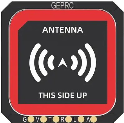
 Design with GNSS GEPRC GEP-M1025 Series GPS in Cirkit Designer
Introduction
The GNSS GEPRC GEP-M1025 Series GPS (Manufacturer Part ID: GEP-M1025-MI) is a high-precision Global Navigation Satellite System (GNSS) module designed specifically for drones, UAVs, and other applications requiring accurate positioning and navigation. This module supports multiple satellite systems, including GPS, GLONASS, Galileo, and BeiDou, ensuring reliable and precise location data even in challenging environments.
Explore Projects Built with GNSS GEPRC GEP-M1025 Series GPS
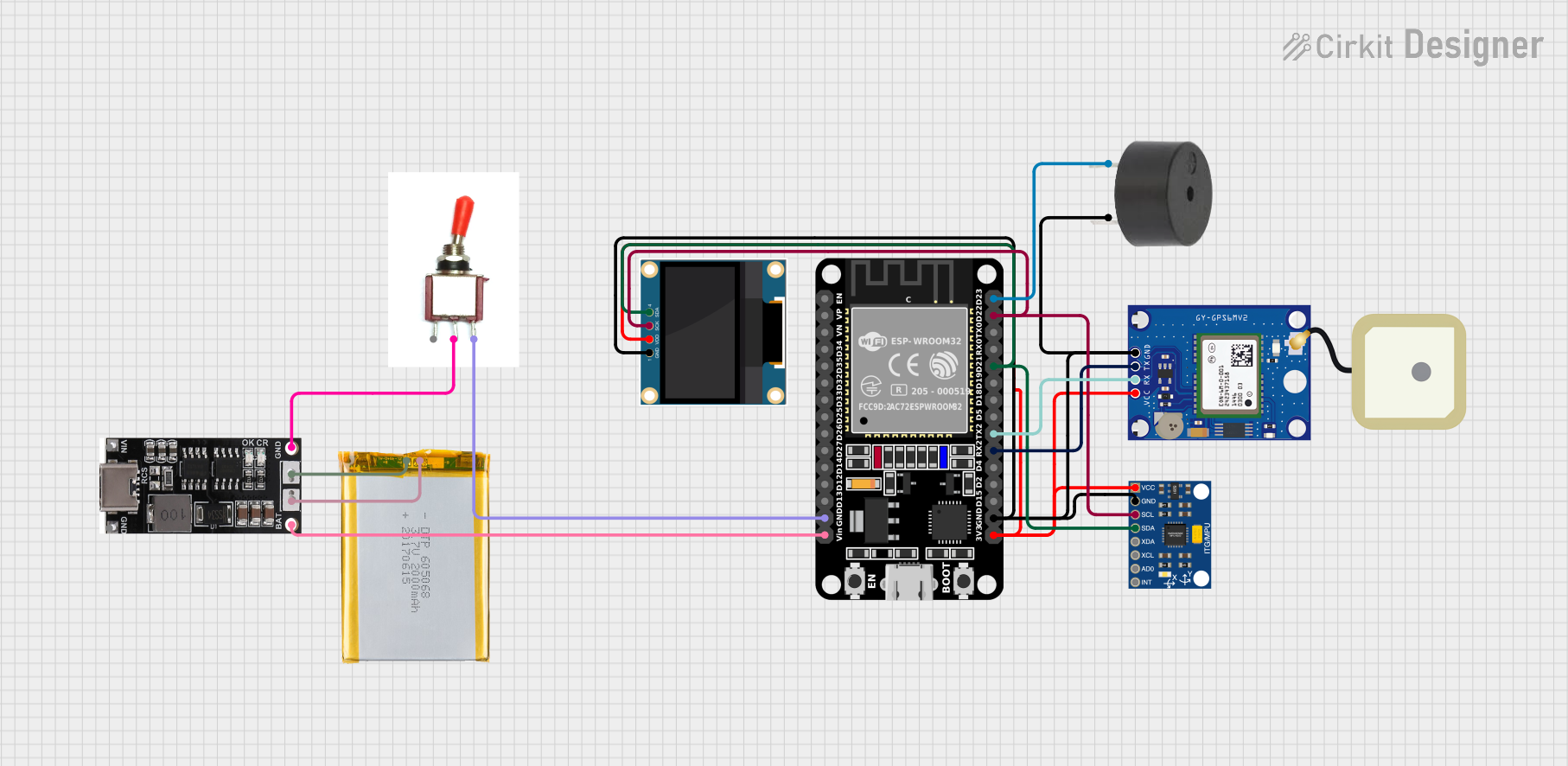 Open Project in Cirkit Designer
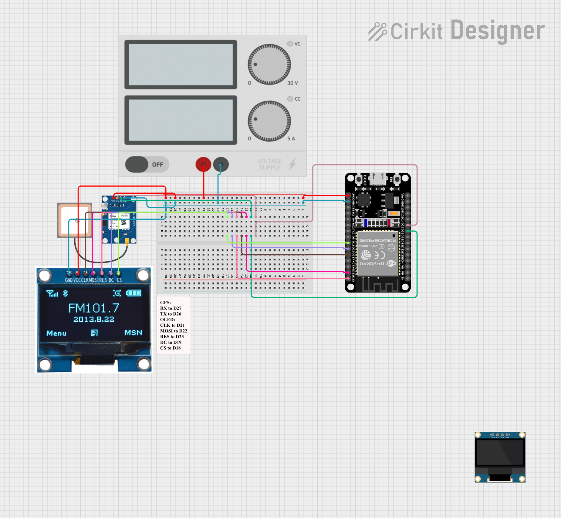 Open Project in Cirkit Designer
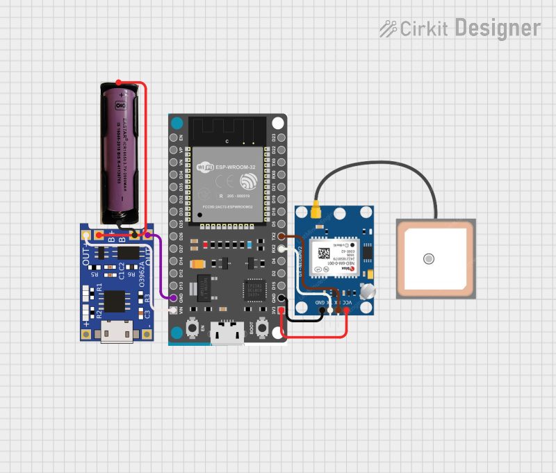 Open Project in Cirkit Designer
 Open Project in Cirkit Designer
Explore Projects Built with GNSS GEPRC GEP-M1025 Series GPS
Open Project in Cirkit DesignerOpen Project in Cirkit DesignerOpen Project in Cirkit DesignerOpen Project in Cirkit DesignerCommon Applications and Use Cases
- Drones and UAVs: For real-time navigation, waypoint tracking, and autonomous flight.
- Robotics: Enabling precise movement and location tracking.
- Surveying and Mapping: High-accuracy positioning for geospatial data collection.
- IoT Devices: Location-based services and tracking.
- Automotive Systems: Navigation and fleet management.
Technical Specifications
The following table outlines the key technical details of the GNSS GEPRC GEP-M1025 Series GPS module:
| Parameter | Specification |
|---|---|
| Satellite Systems Supported | GPS, GLONASS, Galileo, BeiDou |
| Positioning Accuracy | ±1.5 meters (open sky) |
| Update Rate | 1 Hz to 10 Hz |
| Operating Voltage | 3.3V to 5.0V |
| Operating Current | 40 mA (typical) |
| Communication Interface | UART (TTL) |
| Baud Rate | Default: 9600 bps (configurable) |
| Antenna Type | Active ceramic patch antenna |
| Dimensions | 25 mm x 25 mm x 8 mm |
| Weight | 12 grams |
| Operating Temperature | -40°C to +85°C |
Pin Configuration and Descriptions
The GNSS module has a 4-pin interface for easy integration into your system. The pinout is as follows:
| Pin | Name | Description |
|---|---|---|
| 1 | VCC | Power supply input (3.3V to 5.0V) |
| 2 | GND | Ground |
| 3 | TX | UART Transmit (data output from the module) |
| 4 | RX | UART Receive (data input to the module) |
Usage Instructions
How to Use the Component in a Circuit
- Power Supply: Connect the VCC pin to a regulated 3.3V or 5.0V power source and the GND pin to the ground of your circuit.
- UART Communication: Connect the TX pin of the module to the RX pin of your microcontroller (e.g., Arduino UNO) and the RX pin of the module to the TX pin of your microcontroller.
- Antenna Placement: Ensure the active ceramic patch antenna has a clear view of the sky for optimal satellite reception.
- Configuration: Use the default baud rate of 9600 bps or configure it as needed using appropriate software commands.
Important Considerations and Best Practices
- Antenna Orientation: Place the module with the antenna facing upward and away from obstructions or sources of interference.
- Power Supply Stability: Use a stable and noise-free power supply to ensure reliable operation.
- UART Voltage Levels: Ensure the UART voltage levels of your microcontroller match the module's requirements (3.3V or 5.0V).
- Cold Start Time: Allow up to 30 seconds for the module to acquire satellite signals during a cold start.
Example Code for Arduino UNO
Below is an example code snippet to interface the GNSS GEPRC GEP-M1025 Series GPS module with an Arduino UNO:
#include <SoftwareSerial.h>

// Define RX and TX pins for SoftwareSerial
SoftwareSerial gpsSerial(4, 3); // RX = Pin 4, TX = Pin 3

void setup() {
  Serial.begin(9600); // Initialize Serial Monitor at 9600 bps
  gpsSerial.begin(9600); // Initialize GPS module communication at 9600 bps

  Serial.println("GNSS GEPRC GEP-M1025 GPS Module Test");
}

void loop() {
  // Check if data is available from the GPS module
  while (gpsSerial.available()) {
    char gpsData = gpsSerial.read(); // Read one character from the GPS module
    Serial.print(gpsData); // Print the character to the Serial Monitor
  }
}
Note: Connect the GPS module's TX pin to Arduino's Pin 4 and the RX pin to Arduino's Pin 3. Use a logic level shifter if necessary to match voltage levels.
Troubleshooting and FAQs
Common Issues and Solutions
No Data Output from the Module:
- Cause: Incorrect wiring or baud rate mismatch.
- Solution: Verify the connections and ensure the baud rate is set to 9600 bps (or the configured value).
Poor Satellite Signal:
- Cause: Obstructions or interference near the antenna.
- Solution: Relocate the module to an open area with a clear view of the sky.
Module Not Powering On:
- Cause: Insufficient or unstable power supply.
- Solution: Check the power source and ensure it provides 3.3V to 5.0V with adequate current.
Data Corruption in Serial Output:
- Cause: Noise or incorrect UART voltage levels.
- Solution: Use proper shielding for wires and ensure UART voltage compatibility.
FAQs
Q: Can this module be used indoors?
- A: While the module may work indoors, satellite signal reception will be significantly reduced. For best results, use it outdoors with a clear view of the sky.
Q: How do I increase the update rate?
- A: The update rate can be configured using specific NMEA or proprietary commands. Refer to the manufacturer's advanced configuration guide.
Q: Is the module compatible with 5V logic microcontrollers?
- A: Yes, the module supports both 3.3V and 5.0V logic levels, making it compatible with most microcontrollers.
Q: What is the cold start time?
- A: The cold start time is typically 30 seconds under open-sky conditions.
By following this documentation, you can effectively integrate and utilize the GNSS GEPRC GEP-M1025 Series GPS module in your projects.