How to Use TIP31C: Examples, Pinouts, and Specs
Introduction
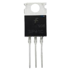
The TIP31C is an NPN bipolar junction transistor (BJT) manufactured by Abhishek, with the part ID "Transistor." It is designed for general-purpose amplification and switching applications. With a maximum collector current of 3A and a maximum collector-emitter voltage of 40V, the TIP31C is a versatile component suitable for a wide range of electronic circuits. Its robust design and high current-handling capability make it ideal for use in audio amplifiers, motor drivers, and power control circuits.
Explore Projects Built with TIP31C
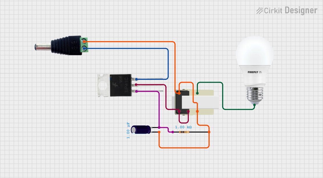
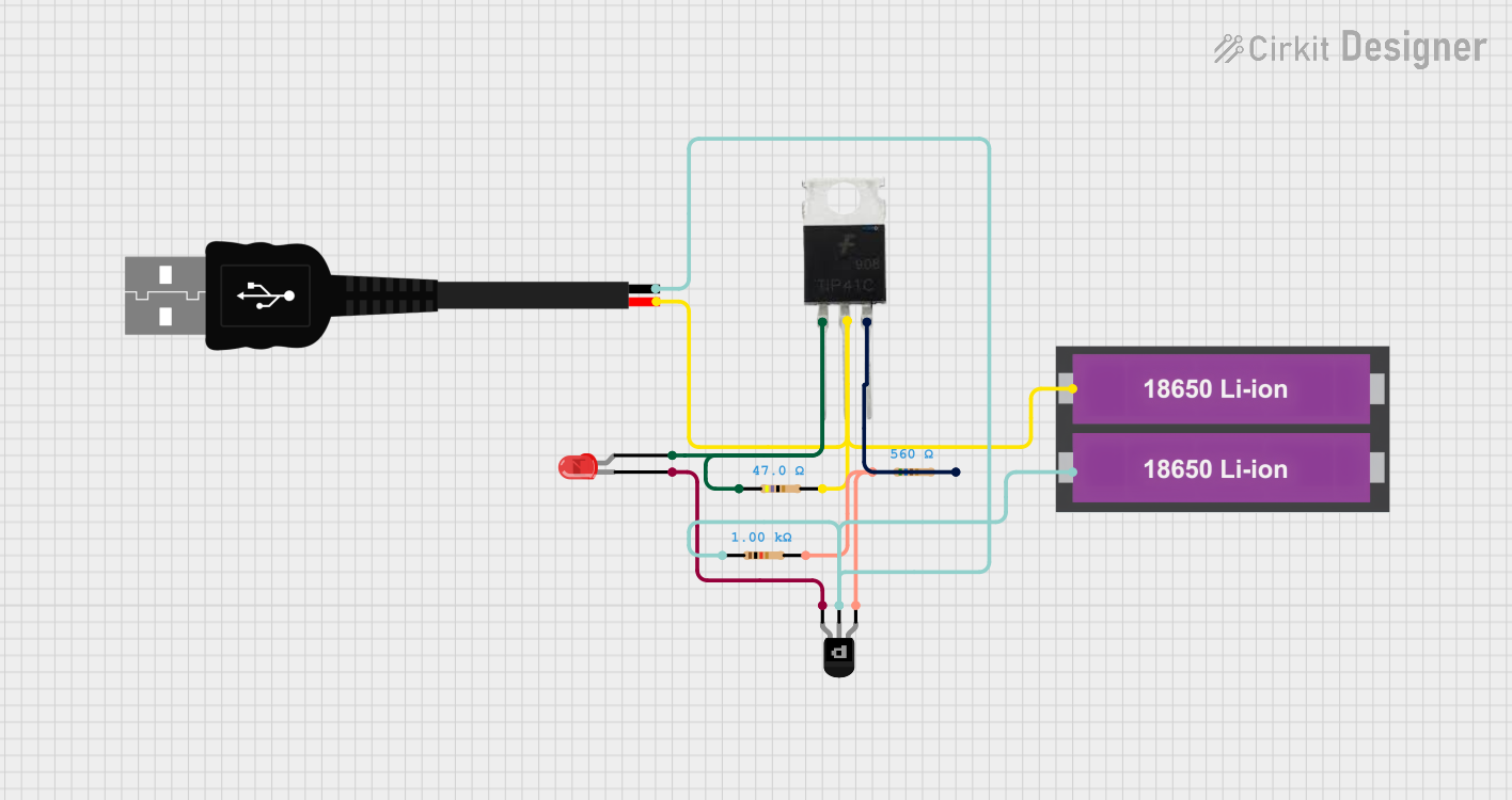

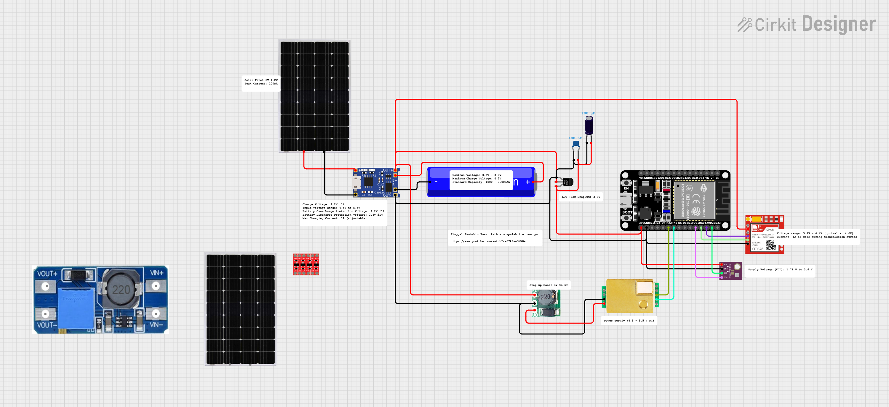
Explore Projects Built with TIP31C
Common Applications
- Audio amplification
- Motor control and drivers
- Power regulation and switching
- Signal amplification in electronic circuits
Technical Specifications
Below are the key technical details of the TIP31C transistor:
| Parameter | Value |
|---|---|
| Manufacturer | Abhishek |
| Part ID | Transistor |
| Transistor Type | NPN |
| Maximum Collector-Emitter Voltage (VCEO) | 40V |
| Maximum Collector Current (IC) | 3A |
| Maximum Power Dissipation (PD) | 40W |
| DC Current Gain (hFE) | 10 to 50 (at IC = 3A) |
| Transition Frequency (fT) | 3 MHz |
| Operating Temperature Range | -65°C to +150°C |
| Package Type | TO-220 |
Pin Configuration
The TIP31C transistor comes in a TO-220 package with three pins. The pin configuration is as follows:
| Pin Number | Pin Name | Description |
|---|---|---|
| 1 | Base (B) | Controls the transistor's operation |
| 2 | Collector (C) | Current flows into this pin |
| 3 | Emitter (E) | Current flows out of this pin |
Usage Instructions
Using the TIP31C in a Circuit
The TIP31C is commonly used in circuits for amplification and switching. Below are the steps to use it effectively:
Determine the Operating Conditions:
- Ensure the collector-emitter voltage (VCEO) does not exceed 40V.
- Ensure the collector current (IC) does not exceed 3A.
Connect the Pins:
- Connect the Base (B) to the control signal through a current-limiting resistor.
- Connect the Collector (C) to the positive side of the load.
- Connect the Emitter (E) to the ground or negative terminal of the power supply.
Base Resistor Calculation:
- Use a resistor to limit the base current (IB) to a safe value. The base current can be calculated using the formula: [ I_B = \frac{I_C}{h_{FE}} ] Choose a resistor value that ensures IB is within the transistor's specifications.
Heat Dissipation:
- If the transistor is operating near its maximum power dissipation (40W), attach a heatsink to the TO-220 package to prevent overheating.
Example: TIP31C with Arduino UNO
The TIP31C can be used to control a DC motor with an Arduino UNO. Below is an example circuit and code:
Circuit Connections
- Connect the TIP31C's Collector (C) to one terminal of the motor.
- Connect the other terminal of the motor to the positive power supply (e.g., 12V).
- Connect the TIP31C's Emitter (E) to the ground.
- Connect the Base (B) to an Arduino digital pin (e.g., D9) through a 1kΩ resistor.
Arduino Code
// TIP31C Transistor Control Example
// This code demonstrates how to control a DC motor using the TIP31C transistor
// and an Arduino UNO. The motor speed is controlled using PWM.

const int motorPin = 9; // Pin connected to the TIP31C base via a resistor

void setup() {
  pinMode(motorPin, OUTPUT); // Set the motor pin as an output
}

void loop() {
  // Gradually increase motor speed
  for (int speed = 0; speed <= 255; speed++) {
    analogWrite(motorPin, speed); // Write PWM signal to the base
    delay(10); // Small delay for smooth speed increase
  }

  // Gradually decrease motor speed
  for (int speed = 255; speed >= 0; speed--) {
    analogWrite(motorPin, speed); // Write PWM signal to the base
    delay(10); // Small delay for smooth speed decrease
  }
}
Important Considerations
- Always use a base resistor to limit the base current and protect the transistor.
- Ensure the power supply voltage and current are within the transistor's limits.
- Use a flyback diode across inductive loads (e.g., motors) to protect the transistor from voltage spikes.
Troubleshooting and FAQs
Common Issues
Transistor Overheating:
- Cause: Exceeding the maximum power dissipation or insufficient heat dissipation.
- Solution: Use a heatsink and ensure the load current is within the specified limits.
No Output from the Transistor:
- Cause: Incorrect base resistor value or insufficient base current.
- Solution: Recalculate the base resistor value and ensure the base current is adequate.
Motor Not Running:
- Cause: Incorrect wiring or insufficient power supply voltage.
- Solution: Double-check the circuit connections and ensure the power supply meets the motor's requirements.
FAQs
Q1: Can the TIP31C be used for AC signals?
A1: Yes, the TIP31C can amplify AC signals, making it suitable for audio and other signal amplification applications.
Q2: What is the maximum PWM frequency for the TIP31C?
A2: The TIP31C has a transition frequency (fT) of 3 MHz, but for practical applications, it is recommended to use PWM frequencies below 20 kHz.
Q3: Can I use the TIP31C without a heatsink?
A3: Yes, but only if the power dissipation is well below 40W. For higher power applications, a heatsink is necessary to prevent overheating.
Q4: Is the TIP31C suitable for switching high-power LEDs?
A4: Yes, the TIP31C can be used to switch high-power LEDs, provided the current and voltage are within its specifications. Use a current-limiting resistor for the LEDs.