How to Use LILYGO TTGO LoRa V1.3 868Mhz ESP32 Chip SX1276 Module 0.9t Inch OLED Screen WiFi And Bluetooth Development Board: Examples, Pinouts, and Specs
Introduction
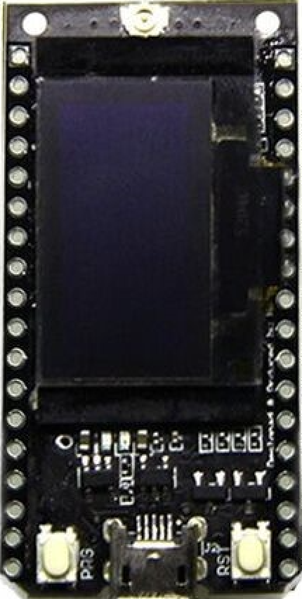
The LILYGO TTGO LoRa V1.3 is a versatile development board designed for IoT (Internet of Things) applications. Manufactured by LilyGO, this board integrates the powerful ESP32 chip, which supports both WiFi and Bluetooth connectivity. Additionally, it features the SX1276 LoRa module for long-range communication and a 0.9-inch OLED screen for displaying real-time data or system status.
This development board is ideal for a wide range of applications, including:
- Long-range IoT communication systems
- Environmental monitoring and sensor networks
- Smart agriculture and industrial automation
- Home automation and remote control systems
- Educational and prototyping projects
With its compact design and rich feature set, the LILYGO TTGO LoRa V1.3 is a popular choice for developers and hobbyists alike.
Explore Projects Built with LILYGO TTGO LoRa V1.3 868Mhz ESP32 Chip SX1276 Module 0.9t Inch OLED Screen WiFi And Bluetooth Development Board

Explore Projects Built with LILYGO TTGO LoRa V1.3 868Mhz ESP32 Chip SX1276 Module 0.9t Inch OLED Screen WiFi And Bluetooth Development Board
Technical Specifications
Key Technical Details
| Parameter | Specification |
|---|---|
| Manufacturer | LilyGO |
| Manufacturer Part ID | LoRa Sensor 1 |
| Microcontroller | ESP32 (dual-core, 32-bit, Tensilica Xtensa LX6) |
| Wireless Connectivity | WiFi (802.11 b/g/n), Bluetooth v4.2 |
| LoRa Module | SX1276 (868 MHz frequency band) |
| Display | 0.9-inch OLED screen (128x32 resolution) |
| Operating Voltage | 3.3V |
| Input Voltage Range | 5V (via USB) or 3.7V (via LiPo battery) |
| Flash Memory | 4MB |
| GPIO Pins | 21 (configurable for digital I/O, ADC, PWM, etc.) |
| Communication Interfaces | UART, SPI, I2C |
| Power Supply Options | USB Type-C or 1S LiPo battery |
| Dimensions | 51mm x 25mm |
Pin Configuration and Descriptions
| Pin Name | Description |
|---|---|
| GND | Ground connection |
| 3V3 | 3.3V power output |
| VIN | Input voltage (5V via USB or 3.7V via LiPo battery) |
| GPIO0 | General-purpose I/O pin (used for boot mode selection) |
| GPIO21 | I2C SDA (data line for I2C communication) |
| GPIO22 | I2C SCL (clock line for I2C communication) |
| GPIO16 | Connected to the OLED screen (used for display control) |
| GPIO17 | Connected to the OLED screen (used for display control) |
| DIO0 | LoRa interrupt pin |
| RST | LoRa reset pin |
| SPI Pins | MISO, MOSI, SCK, CS (used for LoRa communication) |
| BAT | Battery voltage monitoring pin |
Usage Instructions
How to Use the Component in a Circuit
Powering the Board:
- Connect the board to a USB power source using a USB Type-C cable.
- Alternatively, connect a 3.7V LiPo battery to the JST connector on the board.
Programming the Board:
- Install the Arduino IDE and add the ESP32 board support package.
- Select the correct board (
TTGO LoRa32-OLED V1) and port in the Arduino IDE. - Write or upload your code to the board via the USB connection.
Connecting Peripherals:
- Use the GPIO pins to connect sensors, actuators, or other peripherals.
- For I2C devices, connect them to the
GPIO21(SDA) andGPIO22(SCL) pins.
Using the OLED Display:
- The OLED screen is pre-wired to the ESP32 and can be controlled using libraries like
Adafruit_SSD1306orU8g2.
- The OLED screen is pre-wired to the ESP32 and can be controlled using libraries like
Using the LoRa Module:
- The SX1276 LoRa module communicates via SPI. Use libraries like
LoRa.hto send and receive data.
- The SX1276 LoRa module communicates via SPI. Use libraries like
Important Considerations and Best Practices
- Ensure the input voltage does not exceed the specified range to avoid damaging the board.
- Use a proper antenna for the LoRa module to achieve optimal range and performance.
- When using a LiPo battery, monitor the battery voltage to prevent over-discharge.
- Avoid placing the board near strong electromagnetic interference sources, as this may affect wireless communication.
Example Code for Arduino UNO
Below is an example code snippet to display text on the OLED screen and send a LoRa message:
#include <Wire.h>
#include <Adafruit_GFX.h>
#include <Adafruit_SSD1306.h>
#include <LoRa.h>

// OLED display settings
#define SCREEN_WIDTH 128
#define SCREEN_HEIGHT 32
#define OLED_RESET -1
Adafruit_SSD1306 display(SCREEN_WIDTH, SCREEN_HEIGHT, &Wire, OLED_RESET);

// LoRa settings
#define SS 18
#define RST 14
#define DIO0 26

void setup() {
  // Initialize Serial Monitor
  Serial.begin(115200);
  while (!Serial);

  // Initialize OLED display
  if (!display.begin(SSD1306_I2C_ADDRESS, 0x3C)) {
    Serial.println("OLED initialization failed!");
    while (true);
  }
  display.clearDisplay();
  display.setTextSize(1);
  display.setTextColor(SSD1306_WHITE);
  display.setCursor(0, 0);
  display.println("LILYGO TTGO LoRa V1.3");
  display.display();

  // Initialize LoRa module
  if (!LoRa.begin(868E6)) {
    Serial.println("LoRa initialization failed!");
    while (true);
  }
  Serial.println("LoRa initialized successfully.");
}

void loop() {
  // Send a LoRa message
  LoRa.beginPacket();
  LoRa.print("Hello, LoRa!");
  LoRa.endPacket();

  // Update OLED display
  display.clearDisplay();
  display.setCursor(0, 0);
  display.println("Message sent:");
  display.println("Hello, LoRa!");
  display.display();

  delay(2000); // Wait 2 seconds before sending the next message
}
Troubleshooting and FAQs
Common Issues and Solutions
The board is not detected by the Arduino IDE:
- Ensure the correct USB driver is installed for the ESP32.
- Check that the USB cable is functional and supports data transfer.
The OLED screen does not display anything:
- Verify the I2C address of the OLED screen (default is
0x3C). - Ensure the
Adafruit_SSD1306library is correctly installed.
- Verify the I2C address of the OLED screen (default is
LoRa communication is not working:
- Check the antenna connection and ensure it is securely attached.
- Verify that both sender and receiver are configured to use the same frequency and settings.
The board does not power on:
- Confirm that the input voltage is within the specified range.
- If using a LiPo battery, ensure it is charged.
FAQs
Q: Can I use this board with other LoRa frequencies (e.g., 915 MHz)?
A: No, this specific model is designed for the 868 MHz frequency band. For other frequencies, use a compatible model.
Q: What is the maximum range of the LoRa module?
A: The range depends on environmental factors and antenna quality. In open areas, it can reach up to 10 km.
Q: Can I power the board using both USB and a LiPo battery simultaneously?
A: Yes, the board includes a power management circuit to handle both power sources safely.
Q: Is the board compatible with MicroPython?
A: Yes, the ESP32 chip supports MicroPython. You can flash the MicroPython firmware to use it.