How to Use esp: Examples, Pinouts, and Specs
Introduction
The ESP series, developed by Espressif Systems, is a family of low-cost, high-performance Wi-Fi and Bluetooth-enabled microcontrollers. These versatile modules are widely used in Internet of Things (IoT) applications, enabling wireless communication and control in a variety of devices. The ESP series includes popular models such as the ESP8266 and ESP32, which are known for their ease of use, robust features, and extensive community support.
Explore Projects Built with esp

Explore Projects Built with esp
Common Applications and Use Cases
- Home automation systems (e.g., smart lights, thermostats)
- Wireless sensor networks
- Remote monitoring and control
- IoT prototyping and development
- Wearable devices
- Industrial automation
Technical Specifications
Key Technical Details
| Feature | ESP8266 | ESP32 |
|---|---|---|
| Processor | 32-bit Tensilica L106 (80 MHz) | Dual-core Xtensa LX6 (160-240 MHz) |
| Wi-Fi Standard | 802.11 b/g/n | 802.11 b/g/n |
| Bluetooth | Not supported | Bluetooth 4.2 and BLE |
| GPIO Pins | Up to 17 | Up to 36 |
| Operating Voltage | 3.0V - 3.6V | 2.2V - 3.6V |
| Flash Memory | 512 KB to 4 MB | 4 MB (external flash supported) |
| Power Consumption | Low power (deep sleep mode) | Ultra-low power (deep sleep mode) |
| ADC Channels | 1 (10-bit resolution) | 18 (12-bit resolution) |
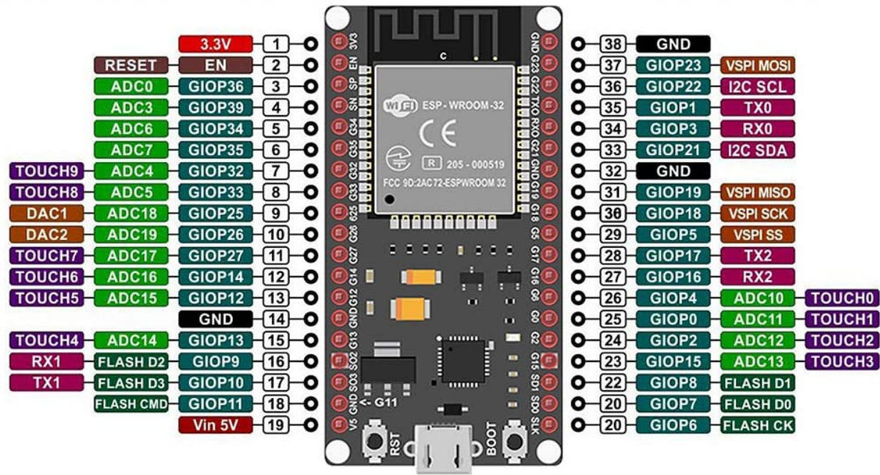
Pin Configuration and Descriptions
ESP8266 Pinout
| Pin Name | Description |
|---|---|
| VCC | Power input (3.3V) |
| GND | Ground |
| TX | UART Transmit |
| RX | UART Receive |
| GPIO0 | General-purpose I/O, boot mode pin |
| GPIO2 | General-purpose I/O |
| GPIO15 | General-purpose I/O, boot mode pin |
| CH_PD | Chip enable (active high) |
| RST | Reset (active low) |
ESP32 Pinout
| Pin Name | Description |
|---|---|
| 3V3 | Power input (3.3V) |
| GND | Ground |
| EN | Enable pin (active high) |
| GPIO0 | General-purpose I/O, boot mode pin |
| GPIO2 | General-purpose I/O |
| GPIO36 | ADC input channel |
| GPIO39 | ADC input channel |
| TX0 | UART Transmit |
| RX0 | UART Receive |
Usage Instructions
How to Use the ESP in a Circuit
- Power Supply: Ensure the ESP module is powered with a stable 3.3V supply. Exceeding this voltage can damage the module.
- Connections:
- Connect the
VCCpin to a 3.3V power source. - Connect the
GNDpin to the ground of your circuit. - Use the
TXandRXpins for UART communication with a microcontroller or USB-to-serial adapter.
- Connect the
- Programming:
- Use a USB-to-serial adapter or a development board (e.g., NodeMCU or ESP32 DevKit) to upload code.
- Install the ESP8266 or ESP32 board package in the Arduino IDE for easy programming.
Important Considerations and Best Practices
- Level Shifting: The ESP operates at 3.3V logic levels. Use a level shifter if interfacing with 5V devices.
- Boot Mode: For ESP8266, ensure GPIO0 is pulled low during boot to enter programming mode.
- Antenna Placement: Avoid placing metal objects near the onboard antenna to ensure optimal Wi-Fi performance.
- Deep Sleep: Use deep sleep mode to minimize power consumption in battery-powered applications.
Example Code for Arduino UNO
Below is an example of using an ESP8266 to connect to a Wi-Fi network and send data to a server:
#include <ESP8266WiFi.h> // Include the ESP8266 Wi-Fi library

const char* ssid = "Your_SSID";       // Replace with your Wi-Fi SSID
const char* password = "Your_Password"; // Replace with your Wi-Fi password
const char* host = "example.com";     // Replace with your server's hostname

void setup() {
  Serial.begin(115200); // Initialize serial communication
  delay(10);

  // Connect to Wi-Fi
  Serial.println("Connecting to Wi-Fi...");
  WiFi.begin(ssid, password);

  while (WiFi.status() != WL_CONNECTED) {
    delay(500);
    Serial.print(".");
  }
  Serial.println("\nWi-Fi connected!");
}

void loop() {
  WiFiClient client;

  // Connect to the server
  if (!client.connect(host, 80)) {
    Serial.println("Connection to server failed!");
    delay(1000);
    return;
  }

  // Send HTTP GET request
  client.println("GET / HTTP/1.1");
  client.println("Host: example.com");
  client.println("Connection: close");
  client.println();

  // Wait for server response
  while (client.connected() || client.available()) {
    if (client.available()) {
      String line = client.readStringUntil('\n');
      Serial.println(line); // Print server response
    }
  }

  client.stop(); // Close the connection
  delay(10000);  // Wait 10 seconds before the next request
}
Troubleshooting and FAQs
Common Issues and Solutions
ESP Not Responding:
- Ensure the module is powered with a stable 3.3V supply.
- Check the connections, especially the
TXandRXpins. - Verify that the correct COM port and baud rate are selected in the Arduino IDE.
Wi-Fi Connection Fails:
- Double-check the SSID and password.
- Ensure the router is within range and supports 2.4 GHz Wi-Fi (ESP modules do not support 5 GHz).
Programming Errors:
- For ESP8266, ensure GPIO0 is pulled low during programming.
- Install the correct board package in the Arduino IDE.
Overheating:
- Avoid overvoltage or excessive current draw.
- Use a heat sink or ensure proper ventilation if the module gets too hot.
FAQs
Q: Can the ESP32 handle multiple tasks simultaneously?
A: Yes, the ESP32 supports dual-core processing and FreeRTOS, allowing multitasking.
Q: Is the ESP8266 compatible with 5V logic?
A: No, the ESP8266 operates at 3.3V logic levels. Use a level shifter for 5V devices.
Q: How do I update the firmware on my ESP module?
A: Firmware updates can be performed using the Espressif Flash Download Tool or the Arduino IDE with the appropriate settings.
Q: Can I use the ESP module without an external microcontroller?
A: Yes, both the ESP8266 and ESP32 can function as standalone microcontrollers.