How to Use ADXL375: Examples, Pinouts, and Specs
Introduction
The ADXL375, manufactured by BMHM with the part ID CJMCU-375, is a low-power, 3-axis accelerometer with a digital output. It is designed for motion sensing applications and features a wide measurement range of ±200 g, high resolution, and built-in features such as tap detection, activity monitoring, and free-fall detection. The ADXL375 communicates via an I²C or SPI digital interface, making it suitable for integration into a wide variety of systems.
Explore Projects Built with ADXL375


Explore Projects Built with ADXL375
Common Applications
- Impact and shock detection
- Sports and fitness equipment
- Industrial vibration monitoring
- Automotive crash detection
- Wearable devices and motion tracking
Technical Specifications
Key Technical Details
| Parameter | Value |
|---|---|
| Measurement Range | ±200 g |
| Resolution | 13-bit |
| Supply Voltage (VDD) | 2.0 V to 3.6 V |
| Interface | I²C, SPI |
| Operating Temperature | -40°C to +85°C |
| Power Consumption | 140 µA (typical) |
| Output Data Rate (ODR) | 0.1 Hz to 3200 Hz |
| Sensitivity | 49 mg/LSB |
| Package Type | LGA-14 (3 mm × 5 mm × 1 mm) |
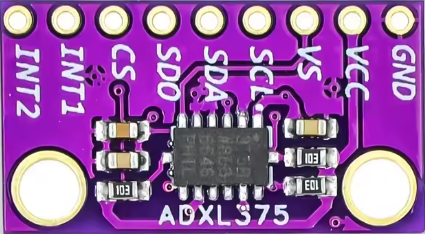
Pin Configuration and Descriptions
The ADXL375 comes in a 14-pin LGA package. Below is the pin configuration:
| Pin Number | Pin Name | Description |
|---|---|---|
| 1 | VDD | Power supply (2.0 V to 3.6 V) |
| 2 | GND | Ground |
| 3 | CS | Chip Select (Active Low, used in SPI mode) |
| 4 | INT1 | Interrupt 1 output |
| 5 | INT2 | Interrupt 2 output |
| 6 | SCL/SCLK | I²C Clock / SPI Clock |
| 7 | SDA/SDI/SDO | I²C Data / SPI Data Input/Output |
| 8 | NC | No Connection |
| 9-14 | NC | No Connection |
Usage Instructions
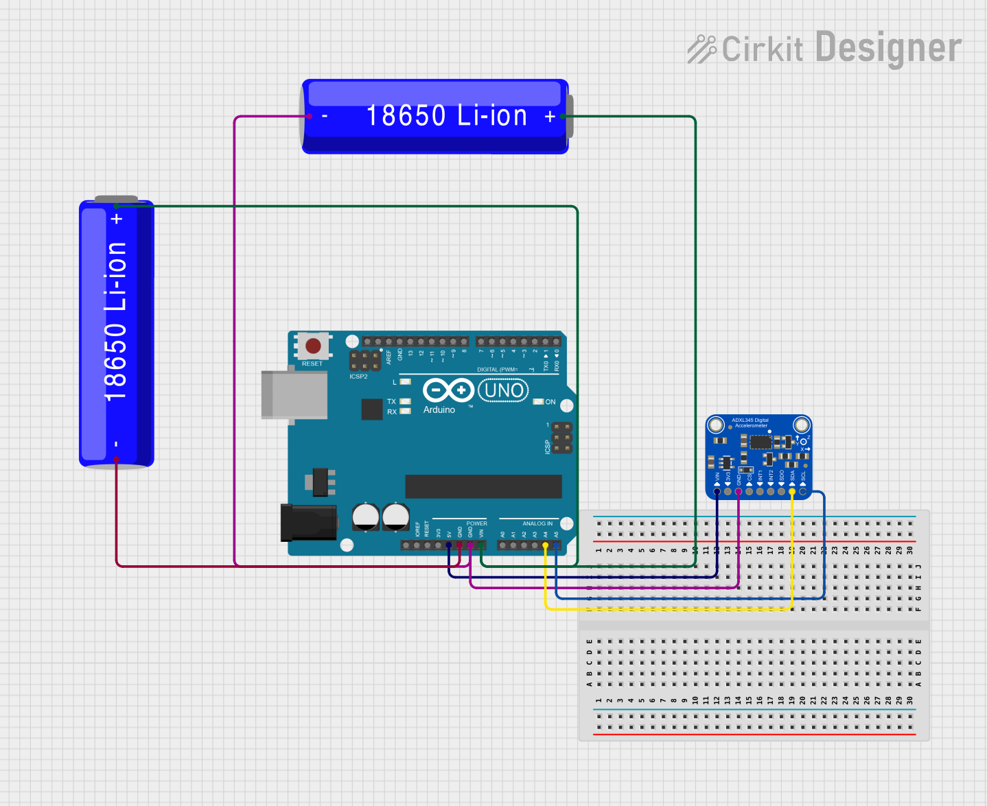
How to Use the ADXL375 in a Circuit
- Power Supply: Connect the VDD pin to a 2.0 V to 3.6 V power source and the GND pin to ground.
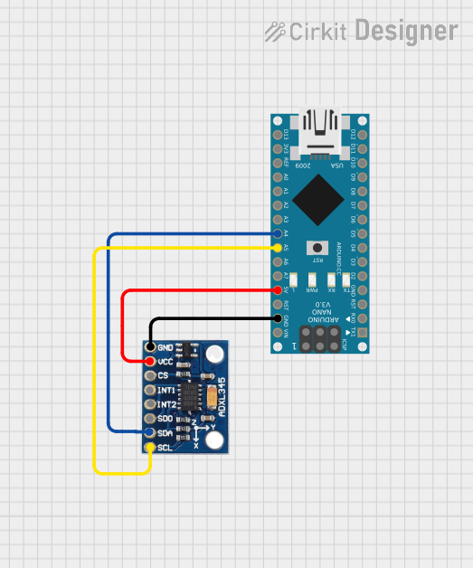
- Interface Selection:
- For I²C communication, connect the SCL and SDA pins to the corresponding I²C lines of your microcontroller.
- For SPI communication, connect the CS, SCLK, and SDI/SDO pins to the SPI lines of your microcontroller.
- Interrupts: Use the INT1 and INT2 pins to configure and monitor interrupts for events like tap detection or free-fall detection.
- Pull-Up Resistors: For I²C communication, ensure pull-up resistors (typically 4.7 kΩ) are connected to the SDA and SCL lines.
- Bypass Capacitor: Place a 0.1 µF ceramic capacitor close to the VDD pin for power supply decoupling.
Important Considerations and Best Practices
- Ensure the ADXL375 is mounted securely to minimize mechanical noise and improve measurement accuracy.
- Use proper filtering techniques to reduce noise in high-vibration environments.
- Configure the output data rate (ODR) and range settings based on your application requirements.
- Avoid exceeding the maximum voltage ratings to prevent damage to the device.
Example Code for Arduino UNO
Below is an example of interfacing the ADXL375 with an Arduino UNO using I²C communication:
#include <Wire.h> // Include the Wire library for I²C communication

#define ADXL375_ADDRESS 0x53 // I²C address of the ADXL375
#define POWER_CTL 0x2D       // Power control register
#define DATA_FORMAT 0x31     // Data format register
#define DATAX0 0x32          // X-axis data register (low byte)

// Function to initialize the ADXL375
void setupADXL375() {
  Wire.begin(); // Initialize I²C communication
  Wire.beginTransmission(ADXL375_ADDRESS);
  Wire.write(POWER_CTL); // Select the power control register
  Wire.write(0x08);      // Set the device to measurement mode
  Wire.endTransmission();

  Wire.beginTransmission(ADXL375_ADDRESS);
  Wire.write(DATA_FORMAT); // Select the data format register
  Wire.write(0x0B);        // Set range to ±200 g and enable full resolution
  Wire.endTransmission();
}

void setup() {
  Serial.begin(9600); // Initialize serial communication
  setupADXL375();     // Initialize the ADXL375
}

void loop() {
  int16_t xData = 0;

  // Read X-axis data
  Wire.beginTransmission(ADXL375_ADDRESS);
  Wire.write(DATAX0); // Request the X-axis data (low byte)
  Wire.endTransmission(false);
  Wire.requestFrom(ADXL375_ADDRESS, 2); // Request 2 bytes of data

  if (Wire.available() == 2) {
    xData = Wire.read();          // Read low byte
    xData |= (Wire.read() << 8);  // Read high byte and combine
  }

  // Convert to g-force (sensitivity = 49 mg/LSB)
  float xG = xData * 0.049;

  // Print the X-axis acceleration
  Serial.print("X-axis: ");
  Serial.print(xG);
  Serial.println(" g");

  delay(500); // Delay for readability
}
Troubleshooting and FAQs
Common Issues
No Communication with the Device
- Cause: Incorrect I²C address or wiring.
- Solution: Verify the I²C address (default is 0x53) and check all connections.
No Data Output
- Cause: Device not in measurement mode.
- Solution: Ensure the POWER_CTL register is configured correctly (set to 0x08).
Inaccurate Readings
- Cause: Excessive noise or improper mounting.
- Solution: Use proper filtering and ensure the device is securely mounted.
Interrupts Not Triggering
- Cause: Interrupts not configured properly.
- Solution: Verify the interrupt configuration registers and ensure the INT1/INT2 pins are connected.
FAQs
Can the ADXL375 operate at 5V?
- No, the maximum supply voltage is 3.6 V. Use a voltage regulator if your system operates at 5V.
What is the maximum sampling rate?
- The maximum output data rate (ODR) is 3200 Hz.
Can I use the ADXL375 for free-fall detection?
- Yes, the ADXL375 has built-in free-fall detection functionality that can be configured via its registers.
Is the ADXL375 suitable for high-impact measurements?
- Yes, with a range of ±200 g, it is ideal for high-impact and shock detection applications.