Cirkit Designer Logo
Cirkit Designer
Your all-in-one circuit design IDE
Home / 
Component Documentation

How to Use Adafruit Mini 8x8 LED Matrix Backpack White: Examples, Pinouts, and Specs

Image of Adafruit Mini 8x8 LED Matrix Backpack White
Cirkit Designer LogoDesign with Adafruit Mini 8x8 LED Matrix Backpack White in Cirkit Designer

Introduction

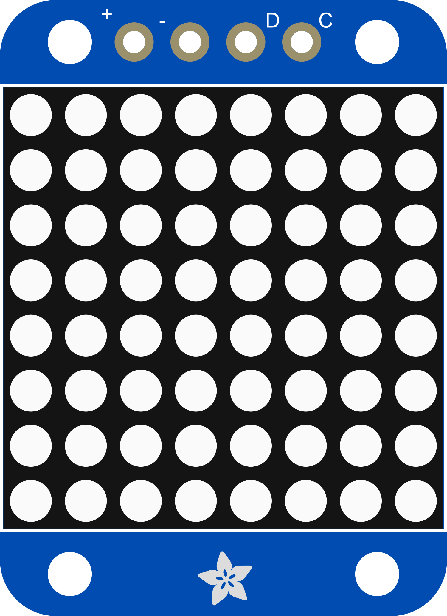
The Adafruit Mini 8x8 LED Matrix Backpack White is a versatile and compact electronic component designed to drive an 8x8 LED matrix. This backpack simplifies the process of controlling multiple LEDs by using an I2C interface, which minimizes the number of pins required from the microcontroller. It is commonly used in projects that require a small visual display, such as wearable electronics, status indicators, or simple games. The built-in constant current drivers ensure uniform brightness, making it ideal for battery-powered applications.

Explore Projects Built with Adafruit Mini 8x8 LED Matrix Backpack White

Use Cirkit Designer to design, explore, and prototype these projects online. Some projects support real-time simulation. Click "Open Project" to start designing instantly!
Arduino UNO WiFi-Controlled LED Matrix Display
Image of SMD2121 Led screen - r4: A project utilizing Adafruit Mini 8x8 LED Matrix Backpack White in a practical application
This circuit consists of an Arduino UNO R4 WiFi microcontroller connected to a 64x32 LED matrix. The Arduino controls the LED matrix by sending signals to various pins to display different colors and patterns, as defined in the embedded code.
Cirkit Designer LogoOpen Project in Cirkit Designer
Arduino-Controlled RGB LED Matrix Display
Image of SMD2121 Led screen: A project utilizing Adafruit Mini 8x8 LED Matrix Backpack White in a practical application
This circuit connects an Arduino UNO R4 WiFi microcontroller to a 64x32 LED matrix display. The Arduino is configured to control the LED matrix, sending color data and control signals to display various colors across the matrix. The embedded code on the Arduino cycles through a range of colors, filling the entire LED matrix with each color in sequence.
Cirkit Designer LogoOpen Project in Cirkit Designer
ESP32-Controlled Dual 8x8 LED Matrix Display with NTP Time Synchronization
Image of time: A project utilizing Adafruit Mini 8x8 LED Matrix Backpack White in a practical application
This circuit features an ESP32 microcontroller connected to two cascaded 8x8 LED matrix displays, powered by a 3.3V battery. The ESP32 drives the displays to show time and other information, with the code indicating functionality for connecting to WiFi, synchronizing time via NTP, and displaying data on the matrices using custom fonts. Additionally, there is a separate 3.3V battery powering a red LED, which appears to function as a simple indicator light.
Cirkit Designer LogoOpen Project in Cirkit Designer
ESP32-Based Smart Weather Station with LED Display and Multiple Sensors
Image of Copy of Zegarek (1): A project utilizing Adafruit Mini 8x8 LED Matrix Backpack White in a practical application
This circuit is a sensor and display system powered by an ESP32 microcontroller. It integrates multiple sensors (BH1750 light sensor, BMP280 pressure sensor, DS3231 RTC, and DS18B20 temperature sensor) and drives a series of MAX7219 8x8 LED matrices for visual output. The ESP32 communicates with the sensors via I2C and controls the LED matrices to display data.
Cirkit Designer LogoOpen Project in Cirkit Designer

Explore Projects Built with Adafruit Mini 8x8 LED Matrix Backpack White

Use Cirkit Designer to design, explore, and prototype these projects online. Some projects support real-time simulation. Click "Open Project" to start designing instantly!
Image of SMD2121 Led screen - r4: A project utilizing Adafruit Mini 8x8 LED Matrix Backpack White in a practical application
Arduino UNO WiFi-Controlled LED Matrix Display
This circuit consists of an Arduino UNO R4 WiFi microcontroller connected to a 64x32 LED matrix. The Arduino controls the LED matrix by sending signals to various pins to display different colors and patterns, as defined in the embedded code.
Cirkit Designer LogoOpen Project in Cirkit Designer
Image of SMD2121 Led screen: A project utilizing Adafruit Mini 8x8 LED Matrix Backpack White in a practical application
Arduino-Controlled RGB LED Matrix Display
This circuit connects an Arduino UNO R4 WiFi microcontroller to a 64x32 LED matrix display. The Arduino is configured to control the LED matrix, sending color data and control signals to display various colors across the matrix. The embedded code on the Arduino cycles through a range of colors, filling the entire LED matrix with each color in sequence.
Cirkit Designer LogoOpen Project in Cirkit Designer
Image of time: A project utilizing Adafruit Mini 8x8 LED Matrix Backpack White in a practical application
ESP32-Controlled Dual 8x8 LED Matrix Display with NTP Time Synchronization
This circuit features an ESP32 microcontroller connected to two cascaded 8x8 LED matrix displays, powered by a 3.3V battery. The ESP32 drives the displays to show time and other information, with the code indicating functionality for connecting to WiFi, synchronizing time via NTP, and displaying data on the matrices using custom fonts. Additionally, there is a separate 3.3V battery powering a red LED, which appears to function as a simple indicator light.
Cirkit Designer LogoOpen Project in Cirkit Designer
Image of Copy of Zegarek (1): A project utilizing Adafruit Mini 8x8 LED Matrix Backpack White in a practical application
ESP32-Based Smart Weather Station with LED Display and Multiple Sensors
This circuit is a sensor and display system powered by an ESP32 microcontroller. It integrates multiple sensors (BH1750 light sensor, BMP280 pressure sensor, DS3231 RTC, and DS18B20 temperature sensor) and drives a series of MAX7219 8x8 LED matrices for visual output. The ESP32 communicates with the sensors via I2C and controls the LED matrices to display data.
Cirkit Designer LogoOpen Project in Cirkit Designer

Common Applications and Use Cases

  • Wearable devices
  • Small display panels for status indicators
  • Custom lighting projects
  • Educational purposes to teach electronics and programming
  • Interactive art installations
  • DIY game consoles

Technical Specifications

Key Technical Details

  • Operating Voltage: 2.5V to 5.5V
  • Communication Interface: I2C
  • I2C Addresses: 0x70 (default) - 0x77 (configurable)
  • LED Color: White
  • Dimensions: 32mm x 32mm x 1.6mm / 1.3" x 1.3" x 0.06"

Pin Configuration and Descriptions

Pin Description
VCC Power supply (2.5V to 5.5V)
GND Ground connection
SDA I2C data line
SCL I2C clock line
ADDR Address selection pin (connect to GND or VCC to set address)
RST Reset pin (optional use)

Usage Instructions

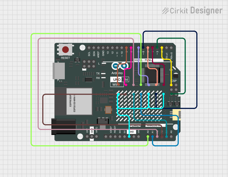
How to Use the Component in a Circuit

  1. Connect the VCC pin to the power supply (2.5V to 5.5V).
  2. Connect the GND pin to the ground of the power supply.
  3. Connect the SDA and SCL pins to the I2C data and clock lines on your microcontroller.
  4. If using multiple backpacks, connect the ADDR pin to VCC or GND to set a unique I2C address for each backpack.
  5. Optionally, connect the RST pin to a digital pin on your microcontroller if you wish to control the reset function.

Important Considerations and Best Practices

  • Ensure that the power supply voltage is within the specified range to prevent damage.
  • Use pull-up resistors on the SDA and SCL lines if they are not already present on the microcontroller board.
  • When daisy-chaining multiple backpacks, ensure that each one has a unique I2C address.
  • Avoid exposing the backpack to moisture or extreme temperatures.

Example Code for Arduino UNO

#include <Wire.h>
#include <Adafruit_GFX.h>
#include <Adafruit_LEDBackpack.h>

Adafruit_8x8matrix matrix = Adafruit_8x8matrix();

void setup() {
  matrix.begin(0x70); // Initialize the matrix with its I2C address
  Wire.begin();       // Join the I2C bus as master
}

void loop() {
  matrix.clear();      // Clear the matrix display
  matrix.drawPixel(0, 0, LED_ON); // Turn on a single LED at (0,0)
  matrix.writeDisplay();  // Write the changes to the display
  delay(500);
  matrix.clear();      // Clear the display again
  matrix.writeDisplay();  // Write the changes to the display
  delay(500);
}

Troubleshooting and FAQs

Common Issues Users Might Face

  • LEDs not lighting up: Check the power supply connections and ensure that the I2C lines are properly connected.
  • Dim or flickering LEDs: Verify that the power supply is within the specified voltage range and that the current is sufficient.
  • I2C communication errors: Ensure that there are pull-up resistors on the SDA and SCL lines and that the I2C address is correctly set.

Solutions and Tips for Troubleshooting

  • Double-check wiring connections and solder joints for any loose connections or shorts.
  • Use a multimeter to verify the voltage levels at the VCC and GND pins.
  • If using multiple backpacks, confirm that each one has a unique I2C address.
  • Consult the microcontroller's documentation to ensure that the I2C lines are correctly configured.

FAQs

Q: Can I use this backpack with a Raspberry Pi? A: Yes, the Adafruit Mini 8x8 LED Matrix Backpack can be used with a Raspberry Pi using the I2C interface.

Q: How do I change the I2C address? A: The I2C address can be changed by connecting the ADDR pin to either GND or VCC. Multiple backpacks can be connected by giving each one a unique address.

Q: Can I control individual LEDs? A: Yes, individual LEDs can be controlled using the drawPixel function in the provided library.

Q: Is it possible to display characters or shapes? A: Yes, the Adafruit GFX library provides functions to draw characters, shapes, and even scroll text across the display.