How to Use 5V 2.5A Buck Converter 6.5-27VDC Input: Examples, Pinouts, and Specs
Introduction
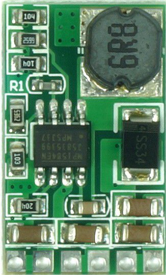
The 5V 2.5A Buck Converter is a DC-DC step-down voltage regulator designed to convert a higher input voltage (ranging from 6.5V to 27V DC) into a stable 5V output. It is capable of delivering up to 2.5A of current, making it suitable for powering a wide range of low-voltage devices. This component is highly efficient, compact, and reliable, making it ideal for applications where power efficiency and size are critical.
Explore Projects Built with 5V 2.5A Buck Converter 6.5-27VDC Input


Explore Projects Built with 5V 2.5A Buck Converter 6.5-27VDC Input
Common Applications and Use Cases
- Powering microcontrollers (e.g., Arduino, Raspberry Pi, ESP32)
- Supplying power to USB devices
- Battery-powered systems
- Robotics and IoT devices
- LED strips and other 5V peripherals
Technical Specifications
Key Technical Details
| Parameter | Value |
|---|---|
| Input Voltage Range | 6.5V to 27V DC |
| Output Voltage | 5V DC |
| Maximum Output Current | 2.5A |
| Efficiency | Up to 95% (depending on load) |
| Switching Frequency | 150 kHz |
| Operating Temperature | -40°C to +85°C |
| Dimensions | Typically 22mm x 17mm x 4mm |
Pin Configuration and Descriptions
| Pin Name | Description |
|---|---|
| VIN | Input voltage pin (6.5V to 27V DC) |
| GND | Ground pin (common ground for input and output) |
| VOUT | Output voltage pin (5V DC) |
Usage Instructions
How to Use the Component in a Circuit
Connect the Input Voltage (VIN):
- Attach the positive terminal of your power source (6.5V to 27V DC) to the
VINpin. - Connect the negative terminal of your power source to the
GNDpin.
- Attach the positive terminal of your power source (6.5V to 27V DC) to the
Connect the Output Load (VOUT):
- Connect the device or circuit requiring 5V to the
VOUTpin. - Ensure the load does not exceed the maximum current rating of 2.5A.
- Connect the device or circuit requiring 5V to the
Verify Connections:
- Double-check all connections to avoid reverse polarity or short circuits.
Power On:
- Turn on the power source and measure the output voltage to confirm it is 5V.
Important Considerations and Best Practices
- Input Voltage Range: Ensure the input voltage is within the specified range (6.5V to 27V DC). Exceeding this range may damage the converter.
- Heat Dissipation: At higher loads, the converter may generate heat. Use proper ventilation or a heatsink if necessary.
- Load Current: Do not exceed the maximum output current of 2.5A to prevent overheating or damage.
- Filtering Capacitors: For improved stability, you can add external capacitors (e.g., 10µF electrolytic and 0.1µF ceramic) near the input and output pins.
Example: Using the Buck Converter with an Arduino UNO
The 5V 2.5A Buck Converter can be used to power an Arduino UNO from a 12V battery. Below is an example circuit and Arduino code to blink an LED:
Circuit Connections
- Connect the 12V battery's positive terminal to the
VINpin of the buck converter. - Connect the 12V battery's negative terminal to the
GNDpin of the buck converter. - Connect the
VOUTpin of the buck converter to the 5V pin of the Arduino UNO. - Connect the
GNDpin of the buck converter to the GND pin of the Arduino UNO. - Connect an LED (with a 220-ohm resistor) to pin 13 of the Arduino UNO.
Arduino Code
// Simple LED blink example for Arduino UNO
// This code assumes an LED is connected to pin 13 with a 220-ohm resistor.

void setup() {
  pinMode(13, OUTPUT); // Set pin 13 as an output
}

void loop() {
  digitalWrite(13, HIGH); // Turn the LED on
  delay(1000);            // Wait for 1 second
  digitalWrite(13, LOW);  // Turn the LED off
  delay(1000);            // Wait for 1 second
}
Troubleshooting and FAQs
Common Issues Users Might Face
No Output Voltage:
- Cause: Incorrect wiring or insufficient input voltage.
- Solution: Verify the input voltage is within the 6.5V to 27V range and check all connections.
Overheating:
- Cause: Excessive load current or poor ventilation.
- Solution: Ensure the load does not exceed 2.5A and provide adequate cooling.
Output Voltage Fluctuations:
- Cause: Insufficient filtering or unstable input voltage.
- Solution: Add external capacitors (e.g., 10µF and 0.1µF) near the input and output pins.
Damaged Converter:
- Cause: Reverse polarity or input voltage exceeding 27V.
- Solution: Use a diode for reverse polarity protection and ensure the input voltage is within range.
Solutions and Tips for Troubleshooting
- Use a multimeter to measure input and output voltages.
- Check for loose or incorrect connections.
- If the converter is not functioning, inspect for visible damage (e.g., burnt components) and replace if necessary.
- For high-current applications, ensure the wires and connectors can handle the current without significant voltage drops.
By following these guidelines, you can effectively use the 5V 2.5A Buck Converter in your projects and troubleshoot any issues that arise.