Cirkit Designer Logo
Cirkit Designer
Your all-in-one circuit design IDE
Home / 
Component Documentation

How to Use DRV8302: Examples, Pinouts, and Specs

Image of DRV8302
Cirkit Designer LogoDesign with DRV8302 in Cirkit Designer

Introduction

The DRV8302 is a three-phase motor driver IC designed for driving brushless DC (BLDC) motors. It integrates a gate driver, current sensing, and protection features, enabling efficient control of motor operation with minimal external components. This component is ideal for applications requiring high-performance motor control, such as robotics, drones, electric vehicles, and industrial automation.

Explore Projects Built with DRV8302

Use Cirkit Designer to design, explore, and prototype these projects online. Some projects support real-time simulation. Click "Open Project" to start designing instantly!
ESP32-Controlled Miniature Golf Course with Interactive Features
Image of aiden: A project utilizing DRV8302 in a practical application
This circuit is designed for an interactive miniature golf course feature, which includes a stepper motor controlled by a DRV8825 driver for a rotating windmill obstacle, two IR sensors for detecting the presence of a golf ball, and two LED strips for visual effects. An ESP32 microcontroller is programmed to manage the sensors, control the stepper motor, drive the LED strips, and interface with a DFPlayer Mini MP3 module for sound effects. The circuit is powered by a 12V power supply with a buck converter to step down the voltage for the logic components, and electrolytic capacitors are used for voltage smoothing.
Cirkit Designer LogoOpen Project in Cirkit Designer
ESP32-Based Industrial Control System with RS485 Communication and I2C Interface
Image of DRIVER TESTER : A project utilizing DRV8302 in a practical application
This circuit integrates a microcontroller with a display, digital potentiometer, IO expander, and opto-isolator board for signal interfacing and isolation. It includes a UART to RS485 converter for serial communication and a power converter to step down voltage for the system. The circuit is designed for control and communication in an isolated and protected environment.
Cirkit Designer LogoOpen Project in Cirkit Designer
ESP32-Based Vibration Motor Controller with I2C IO Expansion
Image of VIBRATYION: A project utilizing DRV8302 in a practical application
This circuit features an ESP32 Wroom Dev Kit microcontroller interfaced with an MCP23017 I/O expansion board via I2C communication, utilizing GPIO 21 and GPIO 22 for SDA and SCL lines, respectively. A vibration motor is controlled by an NPN transistor acting as a switch, with a diode for back EMF protection and a resistor to limit base current. The ESP32 can control the motor by sending signals to the MCP23017, which then interfaces with the transistor to turn the motor on or off.
Cirkit Designer LogoOpen Project in Cirkit Designer
A-Star 32U4 Mini Controlled Servo with VL53L8CX Time-of-Flight Distance Sensing
Image of Servo con distance sensor: A project utilizing DRV8302 in a practical application
This circuit features an A-Star 32U4 Mini microcontroller connected to a VL53L8CX Time-of-Flight distance sensor and a servo motor. The microcontroller powers both the sensor and the servo, and it is configured to communicate with the sensor via I2C (using pins 2 and 3 for SDA and SCL, respectively) and to control the servo via a PWM signal on pin 10. The purpose of the circuit is likely to measure distances and respond with movements of the servo based on the sensor readings.
Cirkit Designer LogoOpen Project in Cirkit Designer

Explore Projects Built with DRV8302

Use Cirkit Designer to design, explore, and prototype these projects online. Some projects support real-time simulation. Click "Open Project" to start designing instantly!
Image of aiden: A project utilizing DRV8302 in a practical application
ESP32-Controlled Miniature Golf Course with Interactive Features
This circuit is designed for an interactive miniature golf course feature, which includes a stepper motor controlled by a DRV8825 driver for a rotating windmill obstacle, two IR sensors for detecting the presence of a golf ball, and two LED strips for visual effects. An ESP32 microcontroller is programmed to manage the sensors, control the stepper motor, drive the LED strips, and interface with a DFPlayer Mini MP3 module for sound effects. The circuit is powered by a 12V power supply with a buck converter to step down the voltage for the logic components, and electrolytic capacitors are used for voltage smoothing.
Cirkit Designer LogoOpen Project in Cirkit Designer
Image of DRIVER TESTER : A project utilizing DRV8302 in a practical application
ESP32-Based Industrial Control System with RS485 Communication and I2C Interface
This circuit integrates a microcontroller with a display, digital potentiometer, IO expander, and opto-isolator board for signal interfacing and isolation. It includes a UART to RS485 converter for serial communication and a power converter to step down voltage for the system. The circuit is designed for control and communication in an isolated and protected environment.
Cirkit Designer LogoOpen Project in Cirkit Designer
Image of VIBRATYION: A project utilizing DRV8302 in a practical application
ESP32-Based Vibration Motor Controller with I2C IO Expansion
This circuit features an ESP32 Wroom Dev Kit microcontroller interfaced with an MCP23017 I/O expansion board via I2C communication, utilizing GPIO 21 and GPIO 22 for SDA and SCL lines, respectively. A vibration motor is controlled by an NPN transistor acting as a switch, with a diode for back EMF protection and a resistor to limit base current. The ESP32 can control the motor by sending signals to the MCP23017, which then interfaces with the transistor to turn the motor on or off.
Cirkit Designer LogoOpen Project in Cirkit Designer
Image of Servo con distance sensor: A project utilizing DRV8302 in a practical application
A-Star 32U4 Mini Controlled Servo with VL53L8CX Time-of-Flight Distance Sensing
This circuit features an A-Star 32U4 Mini microcontroller connected to a VL53L8CX Time-of-Flight distance sensor and a servo motor. The microcontroller powers both the sensor and the servo, and it is configured to communicate with the sensor via I2C (using pins 2 and 3 for SDA and SCL, respectively) and to control the servo via a PWM signal on pin 10. The purpose of the circuit is likely to measure distances and respond with movements of the servo based on the sensor readings.
Cirkit Designer LogoOpen Project in Cirkit Designer

Common Applications and Use Cases

  • Brushless DC motor control in robotics and drones
  • Electric vehicle motor drivers
  • Industrial automation systems
  • HVAC systems
  • Power tools and appliances

Technical Specifications

Key Technical Details

  • Operating Voltage Range: 8 V to 60 V
  • Gate Drive Current: 1.7 A source, 2.3 A sink
  • Integrated Buck Converter: Adjustable output voltage (up to 60 V input, 7.5 V output)
  • Current Sensing: Integrated shunt amplifier with adjustable gain
  • PWM Input Frequency: Up to 200 kHz
  • Protection Features: Overcurrent, overtemperature, and undervoltage lockout
  • Package: HTSSOP-48 with PowerPAD for thermal management

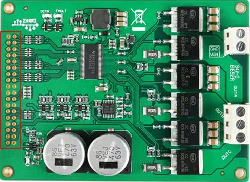
Pin Configuration and Descriptions

The DRV8302 comes in a 48-pin HTSSOP package. Below is a summary of key pins:

Pin Name Type Description
PVDD Power Main power supply input for the motor driver (8 V to 60 V).
GND Ground Ground connection for the IC.
GHx, GLx Output High-side (GHx) and low-side (GLx) gate drive outputs for the three motor phases.
SHx Input/Output Source connection for high-side FETs.
SP/SM Input Current sense amplifier inputs for phase current measurement.
EN_GATE Input Enables the gate driver when set high.
PWM_A, PWM_B Input PWM inputs for controlling motor phases.
VREG Output Regulated voltage output from the internal buck converter.
OC_ADJ Input Adjusts the overcurrent protection threshold.
FAULT Output Fault indicator pin (active low).

For a complete pinout, refer to the DRV8302 datasheet.

Usage Instructions

How to Use the DRV8302 in a Circuit

  1. Power Supply: Connect the PVDD pin to a power supply within the range of 8 V to 60 V. Ensure proper decoupling capacitors are placed close to the IC to minimize noise.
  2. Gate Drive: Connect the GHx and GLx pins to the gates of external MOSFETs for each motor phase. Use low-resistance, high-speed MOSFETs for optimal performance.
  3. Current Sensing: Connect shunt resistors to the SP and SM pins for phase current measurement. Adjust the gain of the current sense amplifier as needed.
  4. PWM Control: Provide PWM signals to the PWM_A and PWM_B pins to control motor speed and direction.
  5. Enable Gate Driver: Set the EN_GATE pin high to enable the gate driver. Use a pull-down resistor to ensure the pin is low during power-up.
  6. Fault Monitoring: Monitor the FAULT pin for any error conditions, such as overcurrent or overtemperature.

Important Considerations and Best Practices

  • Thermal Management: Use a proper heatsink or ensure good PCB thermal design to dissipate heat from the PowerPAD.
  • Decoupling: Place high-quality ceramic capacitors (e.g., 0.1 µF and 10 µF) close to the PVDD and VREG pins to reduce noise and stabilize the power supply.
  • Protection: Configure the OC_ADJ pin to set the overcurrent protection threshold based on your application requirements.
  • Startup Sequence: Ensure the EN_GATE pin is low during power-up to prevent unintended motor operation.

Example Code for Arduino UNO

Below is an example of how to control the DRV8302 using an Arduino UNO:

// Define PWM pins for motor control
const int pwmA = 9;  // Connect to PWM_A pin of DRV8302
const int pwmB = 10; // Connect to PWM_B pin of DRV8302
const int enablePin = 8; // Connect to EN_GATE pin of DRV8302

void setup() {
  // Set up pins as outputs
  pinMode(pwmA, OUTPUT);
  pinMode(pwmB, OUTPUT);
  pinMode(enablePin, OUTPUT);

  // Enable the gate driver
  digitalWrite(enablePin, HIGH);

  // Initialize PWM signals
  analogWrite(pwmA, 128); // 50% duty cycle
  analogWrite(pwmB, 0);   // 0% duty cycle (motor stopped)
}

void loop() {
  // Example: Ramp up motor speed
  for (int speed = 0; speed <= 255; speed++) {
    analogWrite(pwmA, speed); // Increase duty cycle on PWM_A
    delay(10);                // Small delay for smooth ramp-up
  }

  // Example: Ramp down motor speed
  for (int speed = 255; speed >= 0; speed--) {
    analogWrite(pwmA, speed); // Decrease duty cycle on PWM_A
    delay(10);                // Small delay for smooth ramp-down
  }
}

Troubleshooting and FAQs

Common Issues and Solutions

  1. Motor Does Not Spin:

    • Ensure the EN_GATE pin is set high to enable the gate driver.
    • Verify that the PWM signals are being generated correctly.
    • Check the connections to the external MOSFETs and motor phases.
  2. Overcurrent Fault:

    • Verify the shunt resistor values and ensure they are appropriate for the motor current.
    • Adjust the OC_ADJ pin to increase the overcurrent protection threshold if necessary.
  3. Overheating:

    • Ensure proper thermal management by using a heatsink or optimizing PCB layout.
    • Check for excessive current draw from the motor.
  4. Fault Pin Active (Low):

    • Check for fault conditions such as overcurrent, undervoltage, or overtemperature.
    • Reset the fault by toggling the EN_GATE pin low and then high.

FAQs

  • Can the DRV8302 drive a brushed DC motor? No, the DRV8302 is specifically designed for three-phase brushless DC motors.

  • What type of MOSFETs should I use with the DRV8302? Use low-resistance, high-speed N-channel MOSFETs rated for the motor's voltage and current.

  • How do I adjust the current sense amplifier gain? The gain can be adjusted using external resistors connected to the SP and SM pins. Refer to the datasheet for detailed calculations.

  • What is the maximum PWM frequency supported? The DRV8302 supports PWM frequencies up to 200 kHz. Ensure your microcontroller can generate PWM signals within this range.