How to Use PS2 Controller: Examples, Pinouts, and Specs
Introduction
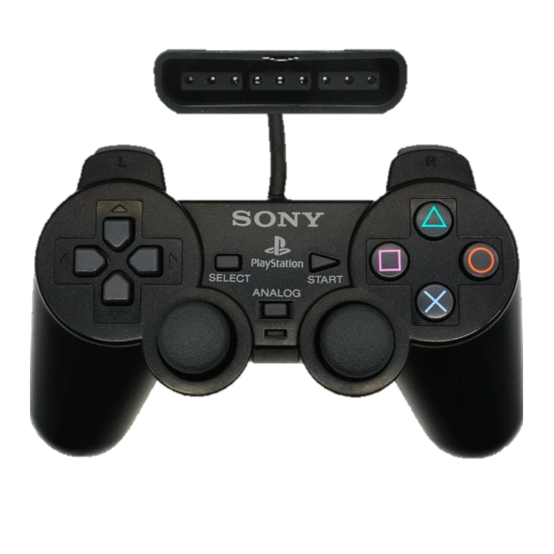
The Analog PS2 Controller by Sony is a game controller designed for the PlayStation 2 console. It features a combination of digital and analog input methods, including a directional pad, two analog sticks, and multiple buttons. This versatile input device is widely used not only for gaming but also in DIY electronics projects, robotics, and other applications requiring user input.
Explore Projects Built with PS2 Controller


Explore Projects Built with PS2 Controller
Common Applications and Use Cases
- Gaming on the PlayStation 2 console
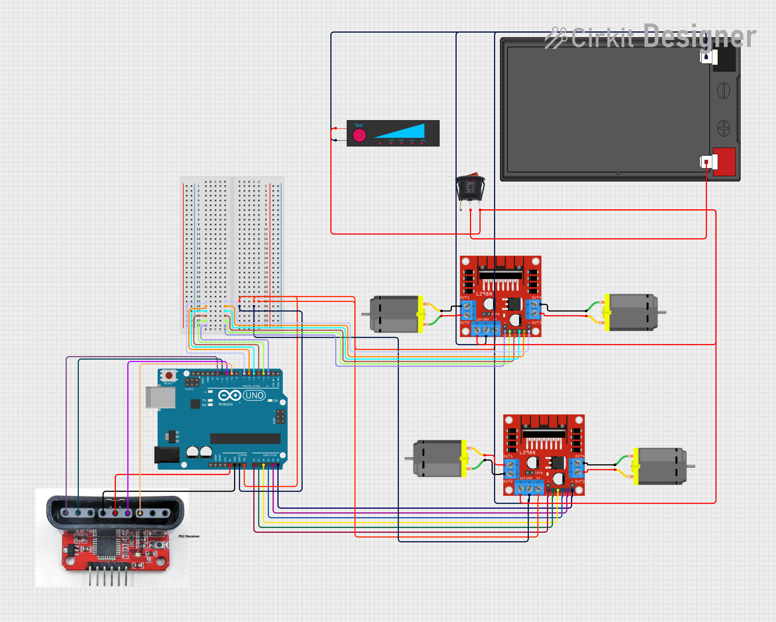
- Robotics control systems
- DIY electronics projects for user input
- Remote-controlled vehicles
- Custom human-machine interface (HMI) designs
Technical Specifications
Key Technical Details
| Parameter | Specification |
|---|---|
| Manufacturer | Sony |
| Part ID | Analog PS2 Controller |
| Communication Protocol | Serial (SPI-like protocol) |
| Operating Voltage | 3.3V to 5V |
| Current Consumption | ~5mA (idle), ~15mA (active) |
| Number of Buttons | 12 (including Start, Select, and L3/R3) |
| Analog Sticks | 2 (X and Y axes for each stick) |
| Cable Length | ~2 meters |
| Connector Type | Proprietary PS2 connector |
Pin Configuration and Descriptions
The PS2 controller uses a proprietary connector with the following pinout:
| Pin Number | Name | Description |
|---|---|---|
| 1 | Data | Serial data line (controller to host) |
| 2 | Command | Serial command line (host to controller) |
| 3 | VCC | Power supply (3.3V to 5V) |
| 4 | Ground | Ground connection |
| 5 | Attention | Chip select (active low, used to initiate communication) |
| 6 | Clock | Serial clock line (host to controller) |
| 7 | N/C | Not connected (reserved for future use) |
| 8 | ACK | Acknowledge signal (controller to host, optional in some implementations) |
Usage Instructions
How to Use the Component in a Circuit
- Power the Controller: Connect the VCC pin to a 3.3V or 5V power source and the Ground pin to the circuit ground.
- Establish Communication: Use an SPI-like protocol to communicate with the controller. The host device (e.g., microcontroller) sends commands via the Command pin and receives data via the Data pin.
- Chip Select: Use the Attention pin to select the controller for communication. Pull this pin low to initiate communication.
- Clock Signal: Provide a clock signal (typically 250kHz) on the Clock pin to synchronize data transfer.
- Read Button States: Send the appropriate command to the controller and read the button states and analog stick positions from the Data pin.
Important Considerations and Best Practices
- Voltage Compatibility: Ensure the controller's operating voltage matches your circuit. Use a level shifter if your microcontroller operates at 3.3V.
- Debouncing: Implement software debouncing for button inputs to avoid false triggers.
- Timing: Maintain proper timing for the clock and Attention signals to ensure reliable communication.
- Connector: Use a breakout adapter or custom wiring to interface with the proprietary PS2 connector.
Example Code for Arduino UNO
Below is an example of interfacing the PS2 controller with an Arduino UNO to read button states and analog stick positions:
#include <PS2X_lib.h>  // Include the PS2X library for PS2 controller communication

PS2X ps2x;  // Create PS2X object

// Pin definitions for PS2 controller
#define PS2_DAT 12  // Data pin
#define PS2_CMD 11  // Command pin
#define PS2_SEL 10  // Attention pin
#define PS2_CLK 13  // Clock pin

void setup() {
  Serial.begin(9600);  // Initialize serial communication for debugging

  // Initialize the PS2 controller
  int error = ps2x.config_gamepad(PS2_CLK, PS2_CMD, PS2_SEL, PS2_DAT, true, true);

  if (error == 0) {
    Serial.println("PS2 Controller successfully connected!");
  } else {
    Serial.print("Error connecting PS2 Controller: ");
    Serial.println(error);
  }
}

void loop() {
  ps2x.read_gamepad(false, 0);  // Read the controller state

  // Read button states
  if (ps2x.Button(PSB_START)) {
    Serial.println("Start button pressed");
  }
  if (ps2x.Button(PSB_SELECT)) {
    Serial.println("Select button pressed");
  }

  // Read analog stick positions
  int leftStickX = ps2x.Analog(PSS_LX);
  int leftStickY = ps2x.Analog(PSS_LY);
  int rightStickX = ps2x.Analog(PSS_RX);
  int rightStickY = ps2x.Analog(PSS_RY);

  Serial.print("Left Stick: X=");
  Serial.print(leftStickX);
  Serial.print(", Y=");
  Serial.println(leftStickY);

  Serial.print("Right Stick: X=");
  Serial.print(rightStickX);
  Serial.print(", Y=");
  Serial.println(rightStickY);

  delay(100);  // Add a small delay to avoid flooding the serial monitor
}
Troubleshooting and FAQs
Common Issues Users Might Face
Controller Not Responding:
- Ensure the Attention pin is pulled low during communication.
- Verify the power supply voltage and ground connections.
- Check the clock signal frequency (should be ~250kHz).
Incorrect Button States or Analog Values:
- Verify the wiring and pin connections.
- Ensure the correct command sequence is sent to the controller.
- Check for noise or interference on the communication lines.
Library Errors:
- Ensure the PS2X library is correctly installed in the Arduino IDE.
- Verify the pin definitions in the code match your circuit.
Solutions and Tips for Troubleshooting
- Use a logic analyzer or oscilloscope to monitor the communication signals.
- Test the controller on a PlayStation 2 console to confirm it is functioning correctly.
- Double-check the pinout and wiring to avoid misconnections.
- Refer to the PS2X library documentation for additional troubleshooting tips.
By following this documentation, users can effectively integrate the Sony Analog PS2 Controller into their projects and troubleshoot common issues with ease.